
Related Manuals for Sherman digitec DIGIMIG 2OO PULSE


Summary of Contents for Sherman digitec DIGIMIG 2OO PULSE
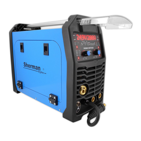
- Page 1 V1.3 19/11/28 USER MANUAL WELDING RECTIFIER synergistic Inverter DIGIMIG 2OO PULSE...
- Page 2 WARNING! Before installing and commissioning, please read these instructions 1. GENERAL Commissioning and operation of the device can be made only after a careful reading of this handbook. Due to the continuous development of technical equipment, some of its functions can be modified and operation may differ in detail from the description in the manual.
- Page 3 Poisoning prevention vapors and gases evolved at the time of welding of coatings for welding electrodes and evaporation of metals: • Use ventilation and exhaust installed in limited air exchange. • Blow fresh air when working in a confined space (tanks) •...
- Page 4 3. GENERAL DESCRIPTION Synergic welding DIGIMIG 200 PULSE is used for manual welding of steel and ferrous metals. It allows welding MMA (covered electrode) MMA pulse, TIG Lift Lift Pulse TIG and MIG / MAG welding. Welding method MIIG / MAG welding can be carried out using single and double pulse.
- Page 5 4.1.1 range parameter adjustment Welding current: MIG 24 - 200 A; MMA: 20 - 200 A; TIG 10 - 200 A Welding voltage: MIG: 17.5 - 24.7 V Wire feed speed: 2 - 14 m / min Inductance: - 99 - + 50% Pre-gas 0 - 10 s Post-gas...
- Page 6 1. Power MIG 2. remote control socket / holder Spool Gun 3. Jack "+" 4. Plug polarization changes 5. Nest "-" 6. The power switch 7. fan 8. The connection connector shielding gas 9. The ground terminal 10. Power Cord 11.
- Page 7 5.1 Wiring 5.1.1 Method MMA Welding the wire ends to terminals (3) and (5) located on the front panel so that the electrode holder was appropriate for the electrode pole. The polarity of the wiring depends on the type of welding electrodes used and is given on the packaging of the electrodes (negative polarity or positive DCEN DCEP). The return line clamp must be carefully mounted on the welded material.
- Page 8 5.1.3 MIG brazing and 5.1.3.1 Welding and brazing gas-shielded Terminal current holder should be connected to MIG (1). Gas conduit from the regulator, lead and attach to the gas nozzle (8) on the back of the device. Plug polarization changes (4) in the socket (3). The negative pole of the source (5) connected to the work piece by means of a wire with a clamp. Plug the device into a power outlet 230V 50Hz.
- Page 9 5.1.3.3 Welding type handle Spool Gun (optional) Terminal current holder should be connected to MIG (1). Plug polarization changes (4) in the socket (3). The negative pole of the source (5) connected to the work piece by means of a wire with a clamp. Plug the device into a power outlet 230V 50Hz. The switch (11) located inside the tray switch position Spool Gun.
- Page 10 6. OPERATION 6.1 Front Panel A - Display The display shows the parameter names and values, numbers of sets of settings stored in memory, and error codes. Voltage (arc length) base current. Only methods for D-PULSE MIG. Range: -50 - 50%. Roasting wire - how long the wire feed continues after extinguishing the arc.
- Page 11 Voltage (arc length) final current (crater filling). Exclusively for MIG modes S2T and S4T. Range: -50 - 50% ARC FORCE. Exclusively for MMA and MMA PULSE. Range: 0 - 100%. FORCE The frequency of the pulse. freq Only for the method of D-Pulse MIG, TIG PULSE and PULSE MMA. Range: PULSE TIG, pulse MMA: 0,1 - 99 Hz; D-Pulse MIG 0.5 - 5 Hz.
- Page 12 Range: 0.1 - 25.5 sec The plate thickness. tick Exclusively for MIG / MAG welding modes MIG SYN. PULSE PULSE-D. The adjustment range depends on the type of material and the diameter of the welding wire. VRD function - it lowers the voltage at no-load. Only for MMA. The adjustment range - ON (On) / Off (Off).
- Page 13 Pressing and releasing the torch will Pre-gas and arc ignition and start welding. By pressing and releasing the button will extinguish the arc and Post-gas. Pressing the torch will Pre-gas and arc ignition and start welding the initial shock Hoti. After the time Hott will change the value of the welding current to the set value.
- Page 14 Sptt Spot welding. Pressing the torch will Pre-gas and arc ignition. After the time Sppt will extinguish the arc and Post-gas. Earlier releasing the handle will immediately extinguish the arc and Post-gas. Stop Sptt Sptt Continuous spot welding. Pressing the torch will Pre-gas and arc ignition. After the time Sptt will extinguish the arc. After the time will stop re-ignition of the arc and the cycle will continue until the button is released uchwytu.Wtedy will extinguish the arc and Post-gas.
- Page 15 welding of carbon steel in the shell mixture of Ar / CO welding of carbon steel in the shell mixture of Ar / CO welding of carbon steel in the shell mixture of Ar / CO Recommended mixing ratio of 82% Ar Recommended mixing ratio of 82% Ar Recommended mixing ratio of 82% Ar 18% CO...
- Page 16 - MIG / MAG double pulse. It is the most advanced welding method in which current pulses are in two ranges. It combines the advantages occur during welding of a single pulse, and additionally allows for a very high aesthetic weld face the effect of the so-called scales.
- Page 17 - TIG lift. - welding MMA (covered electrode) of the pulse. Duty freq - welding MMA (coated electrode). I - selection button diameter of the wire electrode The only active during MIG / MAG modes Used to select the diameter of the wire electrode. Selecting the appropriate mode is confirmed by lighting of the LED. J - Button Load Settings Button is used for loading sets of parameters previously saved in the device memory.
- Page 18 7. PARAMETERS 7.1 Method of MMA and MMA PULSE After selecting the MMA or MMA PULSE it is possible to control parameters according to the following table. The welding current can be adjusted by the control knob immediately after switching on or switching the welding method. PULSE MMA Hoti Hoti...
- Page 19 7.3 Method SYN MIG PULSE and PULSE D-SPL MIG During MIG welding device can operate in synergy (SYN MIG pulse DPULSE) and manual (SPL MIG). Synergic mode allows you to select the welding parameters for less experienced users. In this mode, the device automatically adjusts the welding current and wire feed speed depending on the type of material being welded and the filler wire diameter.
- Page 20 pulse width The pulse width is a pulse duration, allows you to adjust the depth of penetration. The increase in width increase the depth of penetration, reduction reduces the amount of heat entering the material, reducing the risk of burnout of thinner plates and smaller components. Lower values ...
- Page 21 • Ensure that the feed rolls are not too tight. Excessive tension wire may cause feeding problems. • Make sure that the handle is equipped with a teflon cartridge guide intended for aluminum. The use of steel elements used to feed the steel wire will cause feeding problems.
- Page 22 2. In the event of initiation of the arc electrodes, wherein the sheath when solidified, creates a non-conductive slag, the pre-clean the tip of the electrode by repeatedly impact against a hard surface until the metal in contact with the work piece. 10.2 TIG 1.
- Page 23 0.8,0.9 0.8,0.9 17 . 5 17 . 5 17 . 5 0.8,0.9 18 . 5 18 . 5 18 . 5 1.0,1.2 19 . 5 19 . 5 19 . 5 1.0,1.2 1.0,1.2 twenty twenty Free outlet Sheet welding welding Welding The diameter of gas flow...
- Page 24 The diameter of the contact tip The diameter of the electrode wire The contribution of lead wire Blue Blue / Red Yellow 12. malfunctioning CAUSES Cause Procedure symptoms No power, signal failure or faulty No connection or loose plug inside the device Check and correct connection of all electrical plugs operation of the unit inside the device...
- Page 25 13. OPERATION MANUAL Operation of the welder DIGIMIG PULSE 200 should take place in an atmosphere free of corrosive components and dusty. Do not place the device in dusty, near the working grinders, etc. Dust and pollution control boards metallic filings, wires and connections inside the unit may cause an electrical short, and consequently damage to the welding machine.
- Page 26 16. SPECIFICATIONS SET 1. Source 1 piece. 2. The welding TW-15 1 piece. 3. Earth cable with a clamp 1 piece. 4. Manual 1 piece. 5. Packaging 1 piece. 17. GUARANTEE Guarantee granted for a period of 12 months for business entities but excluding claims related to or guarantee of 24 months for the consumer from the date of sale.
- Page 27 18. SCHEME ELECTRICAL...
- Page 28 STATEMENT OF COMPLIANCE 01 / DIGIMIG200PULSE / 2019 Manufacturer's authorized representative: TECWELD Peter Polak 41-943 Piekary Slaskie Street. Emerald 21/3/6 branch: 41-909 Bytom ul. 3 Cross POLAND Declare that the said product: inverter welder Trade name: DIGIMIG 200 PULSE Type: MCU 200 MIG PULSE Manufacturer's trademark: to which this declaration relates complies with the following directives of the European Union and...
Need help?
Do you have a question about the DIGIMIG 2OO PULSE and is the answer not in the manual?
Questions and answers