Table of Contents
Advertisement
Quick Links
Advertisement
Table of Contents

Subscribe to Our Youtube Channel
Related Manuals for Sherman digitec DIGIMIG 2OO PULSE

Summary of Contents for Sherman digitec DIGIMIG 2OO PULSE
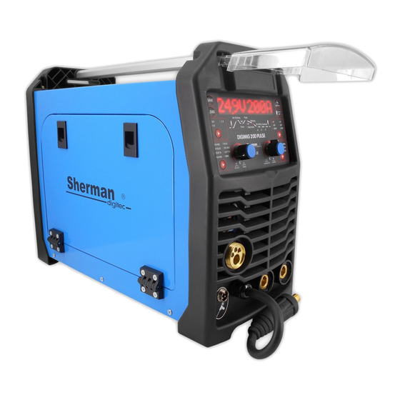
- Page 1 V1.3 19.11.28 USER MANUAL WELDING SYNERGIC RECTIFIER INVERTER DIGIMIG 2OO PULSE...
-
Page 2: General Remarks
ATTENTION! Please read this manual carefully before installing and starting up the device 1. GENERAL REMARKS Commissioning and operation of the device may only be performed after carefully reading these Operating Instructions. Due to the continuous technical development of the device, some of its functions may be modified and their operation may differ in detail from the descriptions in the manual. - Page 3 Prevention of poisoning by vapors and gases released during welding from the electrode coating and metal vaporization: Use ventilation devices and exhausters installed at workstations with limited air exchange, Blow out with fresh air when working in confined spaces (tanks), Use masks and respirators. ...
-
Page 4: Technical Parameters
3. GENERAL DESCRIPTION The synergistic welding machine DIGIMIG 200 PULSE is used for manual welding of steel and non-ferrous metals. It enables welding with MMA (coated electrode), MMA with pulse, TIG Lift, TIG Lift with pulse, and MIG / MAG. Welding with the MIIG / MAG method can be carried out with the use of single and double pulse. -
Page 5: Preparing The Device For Work
4.1.1 Adjustment ranges of parameters Welding current: MIG: 24 - 200 A; MMA: 20 - 200 A; TIG: 10 - 200 A. Welding voltage: MIG: 17.5 - 24.7 V Wire Feed Speed: Inductance: 2 - 14 m / min - 99 - + 50% Gas pre-flow 0 - 10 sec Gas post-flow... - Page 6 1. MIG gun socket 2. Spool Gun remote control / holder socket 3. "+" socket 4. Polarity reversal plug 5. "-" socket 6. Power switch 7. Fan 8. Shielding gas connection stub 9. Earthing clamp 10. Power cord 11. Spool Gun switch 12.
- Page 7 5.1 Connecting the wires 5.1.1 The MMA method The ends of welding cables should be connected to sockets (3) and (5) on the front panel so that the electrode holder has the correct pole for the electrode. The polarity of connecting the welding cables depends on the type of electrode used and is indicated on the package of the electrodes (negative DCEN or positive DCEP).
- Page 8 5.1.3 MIG method and braze welding 5.1.3.1 Welding and braze welding in protective gas shield The torch current clamp should be connected to the MIG torch socket (1). The gas line from the regulator should be lead and fastened to the gas connector (8) on the rear wall of the device. Plug the polarity change (4) into the socket (3). The negative pole of the source (5) should be connected to the work piece by means of a wire with a clamp.
- Page 9 5.1.3.3 Welding with Spool Gun (optional) The torch current clamp should be connected to the MIG torch socket (1). Plug the polarity change (4) into the socket (3). Connect the negative pole of the source (5) to the work piece with a wire with a clamp. Connect the device plug to a 230V 50Hz mains socket.
- Page 10 6. SERVICE 6.1 Front panel A - Display The display shows the names and values of the parameters, the numbers of the sets of settings stored in memory, and the error codes. The voltage (arc length) of the base current. Only for the D-PULSE MIG method.
- Page 11 The final current (crater filling) voltage (arc length). Only for MIG EndU method in S2T and S4T modes. Adjustment range: -50 - 50% ARC FORCE function. FORC Only for MMA and PULSE MMA methods. Adjustment range: 0 - 100%. Pulse frequency. Freq Only for D-PULSE MIG, PULSE TIG and PULSE MMA methods.
- Page 12 Adjustment range: 0.1 - 25.5 s Thickness of the welded material. Tick Only for MIG / MAG method in SYN MIG modes. PULSE and D-PULSE. The adjustment range depends on the type of material to be welded and the wire diameter. VRD function - reduces the voltage in no-load condition.
- Page 13 Pressing and releasing the gun trigger button will cause gas to pre-flow, then strike the arc and start welding. When the button is pressed and released again, the arc will be extinguished and gas will flow out. When the gun button is pressed, gas pre-flows, then strikes the arc and starts welding with the starting current HotI. After the HOTt time has elapsed, the welding current value will change to the set value.
- Page 14 Sptt Spot welding. Pressing the gun button will cause gas to pre-flow and ignite the arc. After the Sppt time has elapsed, the arc will be extinguished and gas post-flow will occur. Early release of the torch button will immediately extinguish the arc and gas post-flow.
- Page 15 welding of carbon steel in the shield of Ar / CO mixture The recommended mixing ratio is 82% Ar 18% CO - argon arc welding of silicon aluminum alloys. - welding of stainless steel in the shield of Ar / CO mixture The recommended mixing ratio is 98% Ar 2% CO - welding of stainless steel in the shield of Ar / CO mixture...
- Page 16 - MIG / MAG welding with double pulse. This is the most advanced a welding method in which current pulses occur in two ranges. It combines the benefits of welding with a single pulse, and additionally allows for a very high aesthetics of the weld face - the so-called scale effect.
- Page 17 - TIG lift welding. - MMA (coated electrode) welding with pulse. Duty Freq - MMA (coated electrode) welding. I - Button for selecting the diameter of the electrode wire The button is active only during MIG / MAG welding in modes Selects the diameter of the filler wire.
-
Page 18: Parameter Settings
7. PARAMETER SETTINGS 7.1 Method of MMA and PULSE MMA After selecting the MMA or PULSE MMA method, it is possible to adjust the parameters according to the table below. The welding current can be adjusted with the adjustment knob immediately after switching the machine on or switching over welding methods. - Page 19 7.3 SYN MIG, PULSE, D-PULSE and SPL MIG method During MIG welding, the device can operate in synergic (SYN MIG, PULSE, DPULSE) and manual (SPL MIG) modes. The synergic mode allows less experienced users to choose welding parameters. In this mode, the device automatically selects the welding current and wire feed speed depending on the type of material to be welded and the diameter of the electrode wire.
- Page 20 Pulse width The width of the pulse is the duration of the pulse, it allows you to adjust the depth of penetration. Increasing the width increases the penetration depth, reducing the amount of heat introduced into the material, reducing the risk of burning through thinner sheets or smaller components.
- Page 21 Make sure the feed rollers are not too tight. Excessive wire tension may cause a feed problem. Make sure the handle is equipped with a Teflon liner designed for aluminum. Using steel components used to feed the steel wire will cause feed problems. ...
- Page 22 2. In the case of arc initiation with electrodes, the coating of which forms a non-conductive slag after hardening, pre- clean the tip of the electrode by hitting a hard surface several times until metallic contact with the welded material is obtained. 10.2 TIG method 1.
- Page 23 0.8,0.9 17.5 0.8,0.9 18.5 0.8,0.9 19.5 1.0,1.2 1.0,1.2 1.0,1.2 Free Diameter Thickness Tension Speed Electricity Gas flow Departure wire welding welding welding sheet metal (l / min) electrodes (mm) (mm) (cm / min) (AND) 0.8,0.9 60~80 16~17 40~50 0.8,0.9 80~100 19~20 40~55 10~15...
- Page 24 Contact tip diameter Wire guide insert The diameter of the electrode wire Blue Blue / Red Yellow 12. CAUSES OF INCORRECT WORK Cause Procedure Symptoms No power, failure signal or No connection or loose plug inside device Check and correct the connections of all device malfunction electrical plugs inside the machine.
-
Page 25: Maintenance Instruction
13. OPERATING INSTRUCTION The operation of the DIGIMIG 200 PULSE welder should take place in an atmosphere free of corrosive components and high dustiness. Do not place the device in dusty places, near working grinders, etc. Dust and contamination with metal filings on control boards, wires and connections inside the device may lead to an electric short circuit, and consequently damage the welding machine. -
Page 26: Warranty
16. SET SPECIFICATION 1. Source 1 piece. 2. TW-15 welding holder 1 piece. 3. Ground cable with a clamp 1 piece. 4. User manual 1 piece. 5. Packaging 1 piece. 17. WARRANTY The warranty is granted for a period of 12 months for business entities, but excluding claims related to the warranty or 24 months for consumers from the date of sale. -
Page 27: Electrical Scheme
18. ELECTRICAL SCHEME... - Page 28 DECLARATION OF CONFORMITY 01 / DIGIMIG200PULSE / 2019 Authorized representative of the manufacturer: TECWELD Piotr Polak 41-943 Piekary Śląskie ul. Szmaragdowa 21/3/6 branch: 41-909 Bytom ul. Krzyżowa 3 POLAND We declare that the following product: Inverter welder Trade name: DIGIMIG 200 PULSE MCU MIG 200 PULSE Type: Manufacturer's trademark:...
Need help?
Do you have a question about the DIGIMIG 2OO PULSE and is the answer not in the manual?
Questions and answers