
Related Manuals for Landoll 9800 Series

Summary of Contents for Landoll 9800 Series
- Page 1 MODEL 9800 SERIES FIELD CULTIVATOR OPERATOR’S MANUAL 1900 NORTH STREET MARYSVILLE, KANSAS 66508 (785) 562-5381 F-216-1000 10/00...
- Page 3 MODEL 9800 SERIES FIELD CULTIVATOR OPERATOR’S MANUAL PURCHASED FROM: DATE ADDRESS: PHONE NO.: SERIAL NO.:...
-
Page 4: Table Of Contents
TABLE OF CONTENTS SECTION DESCRIPTION PAGE NO. INTRODUCTION STANDARD SPECIFICATIONS ASSEMBLY INSTRUCTIONS FRAME ASSEMBLY ........3-5 WING AND EXTENSION INSTALLATION . - Page 5 SAFETY PRECAUTIONS THIS IS THE SAFETY ALERT SYMBOL. IT IS USED TO ALERT YOU TO POTENTIAL INJURY HAZARDS. OBEY ALL SAFETY MESSAGES THAT FOLLOW THIS SYMBOL TO AVOID POSSIBLE INJURY OR DEATH. DANGER DANGER INDICATES AN IMMINENTLY HAZARDOUS SITUA- TION WHICH, IF NOT AVOIDED, WILL RESULT IN DEATH OR SERIOUS INJURY.
-
Page 7: Introduction
INTRODUCTION The Landoll 9800 Series Field Cultivator is a quality product designed to give years of trouble free per- formance. By following each section of this manual, your system will perform as designed for you and your operation. SECTION 1 gives basic instructions on the use of this manual. -
Page 9: Standard Specifications
STANDARD SPECIFICATIONS MODEL NO. OF CUT WIDTH TRANS. TRANS. FRAME SHANKS WIDTH HEIGHT SIZE 980319C 19’-6” 14’-5" 8’-5” 12’-0" 980319S 19’-6” 14’-5" 8’-5” 12’-0" 980321C 21’-6” 14’-5" 9’-5” 12’-0" 980321S 21’-6” 14’-5" 9’-5” 12’-0" 980324C 24’-6" 14’-5" 10’-11" 12’-0" 980324S 24’-6"... - Page 10 MODEL NO. OF CUT WIDTH TRANS. TRANS. FRAME SHANKS WIDTH HEIGHT SIZE 981333C 33’-6” 18’-5” 13’-5” 15’-0" 981333S 33’-6” 18’-5” 13’-5” 15’-0" 981534C 34’-6” 18’-10” 11’-0" 15’-0" 981534S 34’-6” 18’-10” 11’-0" 15’-0" 981336C 36’-6” 18’-5” 14’-11” 15’-0" 981336S 36’-6” 18’-5” 14’-11”...
- Page 11 LANDOLL CORPORATION GENERAL TORQUE SPECIFICATIONS (REV. 4/97) THIS CHART PROVIDES TIGHTENING TORQUES FOR GENERAL PURPOSE APPLICATIONS WHEN SPECIAL TORQUES ARE NOT SPECIFIED ON PROCESS OR DRAWING. ASSEMBLY TORQUES APPLY TO PLATED NUTS AND CAPSCREWS ASSEMBLED WITHOUT SUPPLEMENTAL LUBRICATION (AS RECEIVED CONDITION).
- Page 12 LANDOLL CORPORATION HYDRAULIC FITTING TORQUE SPECIFICATIONS JIC, ORS, & ORB (REV. 10/97) THIS CHART PROVIDES TIGHTENING TORQUES FOR HYDRAULIC FITTING APPLICATIONS WHEN SPECIAL TORQUES ARE NOT SPECIFIED ON PROCESS OR DRAWING. ASSEMBLY TORQUES APPLY TO PLATED CARBON STEEL AND STAINLESS STEEL FITTINGS ASSEMBLED WITHOUT SUPPLEMENTAL LUBRICATION (AS RECEIVED CONDITION).
- Page 13 NOTES:...
-
Page 15: Assembly Instructions
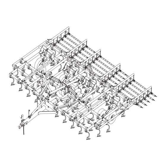
ASSEMBLY INSTRUCTIONS DANGER It is very important that your new 9800 Series Field Cultivator be properly assembled, adjusted and lubricated before use. Illustrations in this sec- TO PREVENT ACCIDENTAL LOWER- tion show proper assembly procedures. Remove ING: paint from grease fittings. Replace any grease fit- 1. - Page 16 Figure 3-1 Frame Assembly...
- Page 17 Figure 3-2 Wing and Extension Assembly...
- Page 18 Figure 3-3 Wing Assembly (981551 & 981554 Models) Figure 3-4 Depth Adjust Rod to Wing Installation...
-
Page 19: Frame Assembly
3-1 FRAME ASSEMBLY WARNING IMPORTANT DO NOT ATTEMPT TO LIFT HEAVY READ ALL SAFETY PRECAUTIONS AT THE PARTS (SUCH AS THE FRAME, ROCK FRONT OF THE SECTION BEFORE ATTEMPT- SHAFT, AND PULL HITCH) MANU- ING ANY OF THE FOLLOWING PROCEDURES. ALLY. - Page 20 Figure 3-5 Manual Adjust Gauge Wheel Installation Figure 3-6 Master and Slave Cylinder Installation...
-
Page 21: Hydraulic Installation
3-4 HYDRAULIC INSTALLATION 3-4.1 Set the depth adjustment to a medium b. Repeat Step 3-4.5a. for other fold cylinder depth (insure that all are set to the same brackets and cylinder anchor bar. c. Attach each fold cylinder bracket assembly depth). - Page 22 Figure 3-7 9803 and 9805 Series Fold Cylinder Bracket...
- Page 23 Figure 3-8 9813 and 9815 Series Fold Cylinder Bracket...
- Page 24 Figure 3-9 Hydraulic Installation (3 section models) 3-10...
- Page 25 FC3800 SERIES HYDRAULIC HOSE (3 SECTION MODELS) ITEM DESCRIPTION USED ON MODEL HOSE ASSEMBLY 36” (NARROW FRAME) HOSE ASSEMBLY 60” (WIDE FRAME) HOSE ASSEMBLY 60” (NARROW FRAME) HOSE ASSEMBLY 84” (WIDE FRAME) HOSE ASSEMBLY 184” (-19, -21) HOSE ASSEMBLY 214” (-24, -27) HOSE ASSEMBLY 240”...
- Page 26 Figure 3-10 Hydraulic Installation (980533 and 980535 models) 3-12...
- Page 27 Figure 3-11 Hydraulic Installation (980533_H model) 3-13...
- Page 28 Figure 3-12 Hydraulic Installation (1 of 2) (980538 model) 3-14...
- Page 29 Figure 3-13 Hydraulic Installation (2 of 2) (980538 model) 3-15...
- Page 30 Figure 3-14 Hydraulic Installation (1 of 2) (980542 and 980545 models) 3-16...
- Page 31 Figure 3-15 Hydraulic Installation (2 of 2) (980542 and 980545 models) 3-17...
- Page 32 9800 SERIES HYDRAULIC HOSE (9805__ MODELS) ITEM PART NUMBER DESCRIPTION USED ON MODEL 1-397-010082 HOSE ASSEMBLY 36” (33’, 33’H, 35’, 38’) 1-397-010299-14 HOSE ASSEMBLY 24” (42’, 45’) 1-397-010264 HOSE ASSEMBLY 214” (33’, 33’H) 1-397-010263 HOSE ASSEMBLY 240” (35’, 38’, 42’, 45’) 1-397-010299-19 HOSE ASSEMBLY 90”...
- Page 33 9800 SERIES HYDRAULIC HOSE (9815__ MODELS) ITEM PART NUMBER DESCRIPTION USED ON MODEL 112186 HOSE ASSEMBLY 22” (34’, 37’, 39’, 42’, 46’, 49’, 51’, 54’) 1-397-010264 HOSE ASSEMBLY 264” (34’, 37’) 1-397-010263 HOSE ASSEMBLY 240” (39’, 42’, 46’, 49’) 1-397-010333 HOSE ASSEMBLY 268”...
- Page 34 Figure 3-16 Hydraulic Installation (981534 model) 3-20...
- Page 35 Figure 3-17 Hydraulic Installation (981537 model) 3-21...
- Page 36 Figure 3-18 Hydraulic Installation (1 of 2) (981539 model) 3-22...
- Page 37 Figure 3-19 Hydraulic Installation (2 of 2) (981539 model) 3-23...
- Page 38 Figure 3-20 Hydraulic Installation (1 of 2) (981542 model) 3-24...
- Page 39 Figure 3-21 Hydraulic Installation (2 of 2) (981542 model) 3-25...
- Page 40 Figure 3-22 Hydraulic Installation (1 of 2) (981546, 981549, 981551, and 981554 models) 3-26...
- Page 41 Figure 3-23 Hydraulic Installation (2 of 2) (981546, 981549, 981551, and 981554 models) 3-27...
-
Page 42: Smv Bracket Installation
Figure 3-24 SMV Bracket Installation 3-5 SMV BRACKET INSTALLATION 3-5.2 Attach SMV emblem to SMV mounting 3-5.1 Install the SMV brackets close to the cen- bracket using 1/4-20 x 1 hex head cap ter of machine on rear frame member. Bolt screws and hex lock nuts. -
Page 43: Shank Installation
Figure 3-25 Installation of Shanks and Clamps 3-6 SHANK INSTALLATION 3-6.1 Install shanks in clamps. (See Figure 3-6.2 Install sweep on shank with 7/16-14 X 3-25). 1-1/2 plow bolt, washers, and nuts provided. a. Spring clamp assembly - Install shank in clamp using 5/8-11X 1-3/4 round head square neck screw and flange lock nut provided. -
Page 44: Pull Hitch Installation (Small Frame Models)
Figure 3-26 Pull Hitch Installation (Small Frame Models) 3-7 PULL HITCH INSTALLATION (SMALL FRAME MODELS) 3-7.1 Install pull hitch to frame using hitch pins 3-7.3 Install jack on pull hitch using 5/8-11 x and 1/4 X 2-1/2 cotter pins (See Figure 1-1/2 hex head cap screw, jack pivot 3-26). -
Page 45: Pull Hitch Installation (Large Frame Models)
Figure 3-27 Pull Hitch Installation (Large Frame Models) 3-8 PULL HITCH INSTALLATION (LARGE FRAME MODELS) IMPORTANT 3-8.1 Install pull hitch to frame using hitch pins and 1/4 X 2-1/2 cotter pins (See Figure Use jack mounting tube on right side of pull 3-27). -
Page 46: Leveling Assembly Installation
Figure 3-28 Leveling Assembly Installation 3-9 LEVELING ASSEMBLY INSTALLATION 3-9.1 Assemble leveling rod to rockshaft using 3-9.2 Assemble the leveling rod to the top hole 1-1/4-7 X 9-1/2 hex head cap screw, pivot in the pivot bracket using pivot pin, 3/8-16 X bushing, flat washer, and hex lock nut (See 4 hex head cap screw, and hex lock nut. -
Page 47: Warning Lights Installation
Figure 3-29 Warning Light Installation 3-10 WARNING LIGHTS INSTALLATION IMPORTANT 3-10.1 Assemble lights to the warning light bracket using 1/4 X 1-1/4 hex head cap Make sure lights are positioned for maximum screws and hex lock nuts. Insure the wires visibility from the rear. -
Page 48: Wing Support Bracket Installation
Figure 3-30 Wing Support Bracket Installation (3-Section Models) 3-11 WING SUPPORT BRACKET INSTALLATION 3-11.1 On all models, install fold lock wing 3-11.3 Fold wings completely and adjust fold lock bracket weldments to frame with u-bolts and wing brackets up to wing frame. 5/8-11 hex lock nuts. - Page 49 Figure 3-31 Wing Support Bracket Installation (5-Section Models) 3-35...
- Page 50 Figure 3-32 Wing Support Bracket Locations (5-Section Models) 3-36...
- Page 51 Figure 3-33 Wing Support Bracket Locations (5-Section Models) 3-37...
-
Page 52: Harrow Installation
3-12.1 See table below for the assembly drawing that will be shipped with your harrow. If lost or missing, this drawing can be ordered from Landoll Corporation. 9800 SERIES HARROW ASSEMBLY DRAWING NUMBERS MODEL 5 BAR CHAIN SPIKE 4 BAR COIL... - Page 53 NOTES: 3-39...
-
Page 55: Operation And Maintenance
OPERATION AND MAINTENANCE DANGER DANGER NEVER ALLOW ANYONE TO RIDE ON WHEN TRANSPORTING THE UNIT, THE 9800 FIELD CULTIVATOR AT ANY PLACE CYLINDER LOCKOUTS IN THE TIME. ALLOWING A PERSON TO RIDE TRANSPORT LOCK POSITION AFTER ON THE MACHINE CAN INFLICT SERI- FULLY EXTENDING THE CYLINDERS. -
Page 56: Tractor Preparation
TRACTOR PREPARATION 4-1.1 Inflate the rear tractor tires equally and add The Landoll 9800 Field Cultivator is designed ballast according to the tractor operator’s to be pulled by tractor equipped with a double lip manual. or clevis type hitch. If your tractor is not equipped 4-1.2... - Page 57 Figure 4-1 Wing Transport Locks 4-4.3 Set the unit working depth. IMPORTANT a. To adjust the depth, lower unit to the ground and completely retract the lift cylinders. IT MAY BE NECESSARY TO ADJUST THE b. Screw the adjustment rod in to decrease the WINGS DIFFERENT THAN THE MAIN FRAME working depth, out to increase the working FOR THE UNIT TO OPERATE LEVEL.
-
Page 58: Harrows
Figure 4-4 Coil Tine Harrow 4-5 HARROWS 4-5.1 Coil Tine (4 bar): Position the spring an- 4-5.2 Chain Spike Harrow: The harrow as as- chor bolt to get the desired pressure on the sembled is set for a working depth of 3 to 5 harrow teeth. -
Page 59: Wheel Bearing Maintenance
Figure 4-5 Chain Spike Harrow 4-6 WHEEL BEARING MAINTENANCE Wheel bearing maintenance should be per- 4-6.4 Repack the bearings using a high-quality formed at the beginning of every season of use. wheel bearing grease. Check the wheel bearings periodically for exces- 4-6.5 Replace the hub with a new seal and the sive end play. -
Page 60: Hydraulic Maintenance
4-7 HYDRAULIC MAINTENANCE 4-7.2 If a cylinder or valve leaks, disassemble 4-7.1 Check the tractor hydraulic fluid level per the parts to determine the cause of the leak. tractor owners manual and after any leakage. Any time a cylinder is opened up, or when- Check fluid level with the cylinders in the re- ever any seal replacement is necessary, it is tracted position. - Page 61 Figure 4-7 Lubrication Points LUBRICATION ITEM DESCRIPTION NO. OF INTERVAL (Hours LUBE unless stated) POINTS Radius rod Leveling rod Rockshaft bearing block 1/block Depth adjust rod assembly - wing Walking beam Yearly Wheel bearing Yearly Depth adjust screw assembly - frame NOTE: LUBE ALL POINTS WITH HIGH GRADE MULTI-PURPOSE GREASE.
-
Page 62: Lubrication
4-9 LUBRICATION 4-9.1 Table 4-4 and Figure 4-7 specifies the number and the period of lubrication points on the 9800 Field Cultivator. Proper mainte- nance of your machine will, under normal op- erating conditions, help to keep it operating at or near its peak performance for an ex- tended period of time. - Page 63 NOTES...
-
Page 65: Troubleshooting Guide
3. SHANKS PLUG WITH RESIDUE A. SHANKS NOT PLACED CORRECTLY: Check with your Landoll dealer. 4. SHANK SPRINGS BREAKING A. SPRING PIVOT BOLT TOO TIGHT: Spring pivot bolt must be loose enough to allow spring plug to pivot so spring is not forced to bend. - Page 66 NOTES:...
Need help?
Do you have a question about the 9800 Series and is the answer not in the manual?
Questions and answers