Advertisement
Quick Links
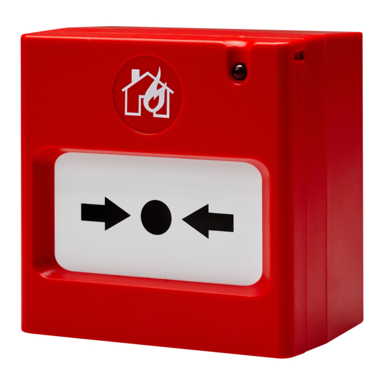
Natron MCP
Wireless addressable
fire alarm manual
ATTENTION: Read carefully this installation Instructions before installing the device!
1. General Description and Working Principle
Natron MCP is a wireless addressable manual call point designed for operation with Natron series
wireless expander modules*. In stand-by mode, the resettable (frangible) call point element is in a
middle position and the status LED is off.
* Refer to the installation manuals of Natron WE-C, Natron WE-A and Natron WE-A/C wireless expander modules for detailed
information about the programming menus and other details.
To initiate a fire alarm or evacuation event, press on the resettable element – it moves down and a color
strip is shown on at its upper side. The call point is in "Fire alarm" condition and the status LED starts
blinking fast. To reset the flexible element back in stand-by mode, use the special key tool included in
the kit - fix the long side of the tool at the call point's bottom side and push it up until flexible element
moves up in middle position – a click is heard. Then reset the fire alarm control panel.
Attention. In case of fire alarm event and no connection between the device and the expander module
are applied the following working algorithms for conservation of the call point power battery:
- The connection between the device and the expander module is lost and after that the call
point is activated. In this case the status LED flashes 3 times and stops.
- The call point is activated, the status LED is blinking fast and after that the connection
between the device and the expander module is lost. In this case the status LED will proceed
blinking fast for 5 minutes and after that will stop if the connection with the expander module is not
restored during that period.
When the connection between the expander module and the device is restored and the call point is still
activated (the color strip is visible), the status LED will proceed blinking fast until resetting the call point.
2. Technical Specifications
Communication range with expander module ......... 1500m
Battery power supply ............................................. 1 x CR123A 3V
Battery life ............................................................. ~10 years
Radio frequency ..................................................... 868MHz
Communication type .............................................. Bidirectional
Communication Protocol ........................................ NATRON TTE
Radio signal modulation type ................................. GFSK
Number of frequency channels ............................... 6 pair channels
Radiated power...................................................... ≤ 20 mW
Receiver category (EN300-220-1) .......................... 1.5
Trace attenuation ................................................... ≥ -90dBm (during the installation)
Test transmission message period ......................... 300s
Type ...................................................................... A
Type of the frangible element ................................ Resettable (flexible)
Operation temperature ........................................... -10°C to +55°C
Related humidity resistance ................................... (93±3)% @ 40°С (no condensation)
Enclosure box type ................................................ ABS
Dimensions ............................................................ 90x57x90mm
Color ...................................................................... RAL 3020 (red)
Protection .............................................................. IP40
Weight (with battery) .............................................. 158g
Mounting ................................................................ Wall, Indoor use
Standards .............................................................. EN 54-11; EN 54-25
EN 54-11:2001/A1:2005
call point
This manual is subject to change without notice!
23
2918
DoP No: 217
EN 54-25:2008
Type A
1
Teletek Electronics JSC
Address: 2 Iliyansko Shose Str,
1220 Sofia, Bulgaria
Advertisement

Related Manuals for Teletek electronics Natron MCP


Summary of Contents for Teletek electronics Natron MCP
- Page 1 This manual is subject to change without notice! 1. General Description and Working Principle Natron MCP is a wireless addressable manual call point designed for operation with Natron series wireless expander modules*. In stand-by mode, the resettable (frangible) call point element is in a middle position and the status LED is off.
- Page 2 3. Installation Place and Mounting Attention: For optimum operation, plan to ensure at least 2m distance between two Natron expander modules and the same minimal distance between each device and the expander module. Mounting holes and orientation of the box bottom Dimensions Structure –...
- Page 3 4. PCB Elements The PCB of the manual call point is factory mounted at the back side of the carrier unit. 1 – Enroll button. The button is used for the following actions: - Enrolling the device to the expander module. - Checking the signal strength.
- Page 4 It is recommended to change it with a brand new. To reset the Natron MCP, power it on with the battery and after that press and hold ENROLL button for 5-7 seconds. The reset is complete when the operation LED on the PCB of the call point flashes 3 times in green, followed from 1 long flash in red and 1 long flash in green.
Need help?
Do you have a question about the Natron MCP and is the answer not in the manual?
Questions and answers