Table of Contents
Advertisement
Advertisement
Table of Contents

Related Manuals for Teletek electronics IRIS


Summary of Contents for Teletek electronics IRIS
- Page 1 ANALOGUE ADDRESABLE FIRE PANEL INSTALLATION MANUAL VERSION 1.0...
- Page 2 This manual contains an information about the limitations in using and operation of the product, as and information about the limits in the responsibility of the manufacturer. Please read the operation manual carefully before starting the installation. ALL RIGHTS RESERVED! This manual is subject to change without a notice! Fire Panel IRIS - Installation Manual...
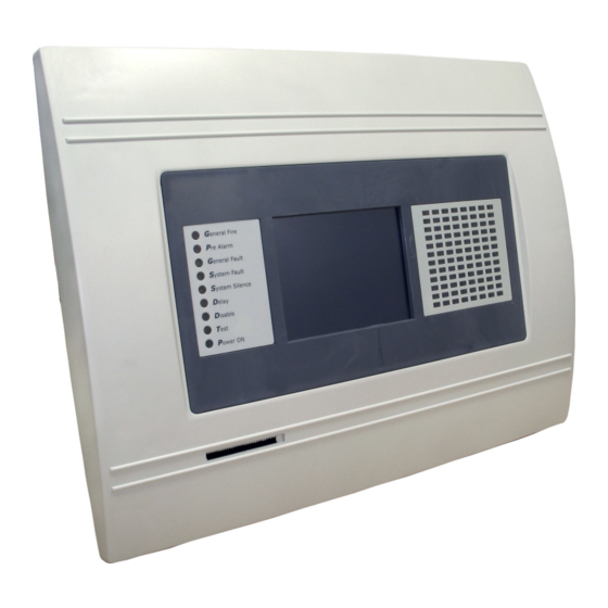
- Page 3 1.1 General Description IRIS is an analogue addressable fire panel with maximum coverage of 96 zones, with 1 or 2 loops and 198 (99 detectors and 99 modules) devices per loop. The panel maintains a System Sensor series 200 protocol.
- Page 4 - Mail Power Supply: ~230V ±10% - Frequency: 50/ 60Hz - Electrical output: 1A ATTENTION: Do not instal the fire panel near power electromagnetic fields (radio equip- ments, electric motors, etc.)! Fire Panel IRIS - Installation Manual...
- Page 5 - Outputs: Sounder, Fire, Fault and Fire Protection - 0,5A, Self-recovering Type - Battery: 10A, Automobile Type List of the additional components, included in the set of the fire panel IRIS: 1. Fuse, Automobile Type, 10A 2. Fuse 2A, Slow Type, for the Power Supply 3.
- Page 6 • Connect the mains supply and earth to the main terminal block BUT DO NOT apply the main electri- cal supply at this stage. • Position the accumulator battery in an upright position and fix the metal clamp. Figure 4 Figure 5 Fire Panel IRIS - Installation Manual...
- Page 7 2.1.2 Flush Mounting • Analogue-addressable fire panel IRIS is provided for flush mounting. In the set of the panel are included two special hinges used for building-in the metal box of the panel in gypsum plaster walls with thickness up to 25mm.
- Page 8 3 - Clamp for supporting the main power supply cable. 4 - Terminal for connection between the mains power supply and the power source. A slow type fuse 12A is situated into the terminal. 5 - Earthing lead. Fire Panel IRIS - Installation Manual...
- Page 9 2.2.3 Main Board The Main Board (Figure 11) is a basic part of the fire panel IRIS. Its function is to control the output devices – sounders, fire detectors, signaling devices, etc. The Main Board could not work independently. Figure 11 – General view of the Main Board of the fire panel.
- Page 10 0,5A. Before connecting the last sounder in the circuit, parallel to it must be added end-of-line resistor 10k. Figure 13. Connecting of sounders. Fire Panel IRIS - Installation Manual...
- Page 11 3 – Place 20 Relay expander module on the Main board, thus the flat interface connectors on the both PCBs to connect to each other. 4 – Fix with suitable bolts 20 Relay expander module to the Main Board. Fire Panel IRIS - Installation Manual...
- Page 12 2. Receives commands from the Main Board and transfers them to the devices connected in the communication line. In the configuration of analogue-addressable fire panel IRIS could be mounted two loop expanders, and thus the maximum number of the addressable devices increases to 396.
- Page 13 fire panel will not be able to communicate with the devices from section 2, it will generate an alarm signal for lost devices and open circuit. Figure 18. IMPORTANT: The maximum number of devices between two iso- lator modules is 30! Fire Panel IRIS - Installation Manual...
- Page 14 Input for connecting the Fault output of the external power supply. +13.8V External power supply input. Before the mains supply is switched on, check the correct connection of each loop, sounder or any other input or output. Fire Panel IRIS - Installation Manual...
- Page 15 flat terminal lug at the end – Figure 20. Never cut or shorten the cable with the built-in thermo resistor, because that will harm the normal charging of the battery! Fire Panel IRIS - Installation Manual...
- Page 16 2.3. Network connection diagram It is possible to connect some individual IRIS fire panels in a network by means of a HUB and TCP/IP proto- col – Figure 21. A supervisor PC, which could follow the current status of the individual fire panels, monitors the current panel state.
- Page 17 The general view of the CONFIGURATION Menu of IRIS Fire Panel is shown on Fig. Screen 1. It gives the installer the possibility to choose the type of the operation, which is necessary to do: 1.
- Page 18 3.2 Devices In the addressable fire panel IRIS are supported periphery and loop devices. With choosing the “Device” but- ton the user/installer enters a menu for choosing the type of the device – Fig. Screen 3. Fig. Screen 3. 3.2.1 Periphery Devices Choosing “Periphery Device”...
- Page 19 20 Relay Expander – I/O24), and on Fig. Screen 7 – the third available periphery device (First Loop expander – LOOP1). Fig. Screen 5 – PSU (Power source) Fig. Screen 6 – I/O24 (Main board + 20 Relay Expander Module) Fire Panel IRIS - Installation Manual...
- Page 20 For ease of introduction, the panel suggests possible devices for se- lection. Information for correspondence of the device types is given in §3.2.2.12 Maintained Loop Devices and Appendix B – Tables for correspondence of the device types. Fire Panel IRIS - Installation Manual...
- Page 21 3.2.2.9 Change Device Type Button Press this button for the panel to provide a compatibility device list of which to choose the most suitable one. The “SELECT NEW DEVICE TYPE” message will be portrayed Fig. Screen 9. Fire Panel IRIS - Installation Manual...
- Page 22 (FIRE) – Fig. Screen 11, is performed by pressing of the respective but- ton and entering of the desired value by means of an additional keypad displayed on the screen. Fig. Screen 11. Fire Panel IRIS - Installation Manual...
- Page 23 LED blinks at every query addressed by the system. In the OFF mode the LED does not reflect any device contact. The LED turns ON in case of a FIRE signal. - Introduce the name of the device – 40 digits. Fire Panel IRIS - Installation Manual...
- Page 24 LED blinks at every query addressed by the system. In the OFF mode the LED does not reflect any device contact. The LED turns ON in case of a FIRE signal. - Introduce the name of the device – 40 digits. Fire Panel IRIS - Installation Manual...
- Page 25 LED blinks at every query addressed by the system. In the OFF mode the LED does not reflect any device contact. The LED turns ON in case of activation at the input. - Introduce the name of the device – 40 digits. Fire Panel IRIS - Installation Manual...
- Page 26 - A number should be set for the zone (1-96), to which the messages from the specific device will be sent, indicating: ALARM, TROUBLE, etc. Fire Panel IRIS - Installation Manual...
- Page 27 Important: Every device can be enabled or disabled. When disabled a “LOOP DEVICE DISA- BLED” message is generated to the respective zone. No signals will be perceived from a disabled device. Device disabling does not terminate after a RESET command. Fire Panel IRIS - Installation Manual...
- Page 28 3.3 Zones The IRIS analogue-programmable fire panel avails of 96 zones. There are separate LED-s to indicate FIRE and PREALARM statuses for each zone. In case of FIRE event - LED is permanently lit. In case of a PRE- ALARM event - LED blinks. To enter the submenu for zone configuration, chose “Zones” button from Program- ming menu –...
- Page 29 • Number of the loop, device address and indication whether it is a module or detector. Only a de vice with an input can be configured. ZONE • Number of zone and event for activation. The possible events by zones are: - FIRE - FAULT - DISABLED - PREALARM Fire Panel IRIS - Installation Manual...
- Page 30 To enter the submenu for outputs configuration choose “Outputs” button from Programming menu – Fig. Screen 2. The general view of the menu for inputs configuration is shown on Fig. Screen 14. Fig. Screen 14 - Menu for introducing output parameters. Fire Panel IRIS - Installation Manual...
- Page 31 LATCHED or the output LATCHED. 3.5.6 Menu for selection of the inputs, controlling the outputs Fig. Screen 15 3.5.7 Mode LATCHED – deleted only after RESET. UNLATCHED – monitors the status. Fire Panel IRIS - Installation Manual...
- Page 32 “Apply” button will be activated. Pressing that will save the new access level. There must be at least one code in the system with an access code 3! The program disallows editing a level of access (3) if it is the only one! Fire Panel IRIS - Installation Manual...
- Page 33 Choose the button “Date” from the Maintenance Menu to set the current date – Fig. Screen 19. The desired date can be set with the buttons for se- lecting the day, month and year. Fig. Screen 19. Fire Panel IRIS - Installation Manual...
- Page 34 The times are set for every day of the week. By default the station is in nighttime mode. 4.5 Output Delay Introduction Choose the button “Output Delay” from the Maintenance Menu to set the output delay – Fig. Screen 22. Fig. Screen 22 Fire Panel IRIS - Installation Manual...
- Page 35 (the time when the delay is deactivated) are introduced. The times are set for every day of the week. During turned on “Delay” the LED is active. Fire Panel IRIS - Installation Manual...
- Page 36 Fig. Screen 24. 4.7 Testing The addressable fire panel IRIS has an option for testing of zone functioning and the LED-indication of the panel. To make a test, choose the “Test” button from Programming Menu – Fig. Screen 17. On the displayed screen the user/installer could choose which test to perform –...
- Page 37 – see Fig. Screen 8, part Programming. Note: From the disabling menu you can directly enter in the loop devices configuration menu (Fig. Screen 8) as choose “Loop Devices” button (Fig. Screen 26). Fire Panel IRIS - Installation Manual...
-
Page 38: Software Version
From the menu for disabling introduction – Fig. Screen 26, the user/installer can disable or enable the moni- tored outputs of the IRIS fire panel – Sounder, Fire Brigade, Fire Protection and Fire Routing – Fig. Screen 29. Fig. Screen 29. - Page 39 The message “Calibration Unsuccessful!!!” will be displayed if the calibration has been unsuccessful, the newly introduced data will be ignored and after pressing of any part of the display, the program returns to the main menu. Fig. Screen 30. Fire Panel IRIS - Installation Manual...
- Page 40 Used for accessing the alarm review window. The button contains a counter of the current alarms in the panel. 5.1.4 Error Access Button Used for accessing the error review window. 5.1.5 Warning Access Button Used for accessing the warnings review window. Fire Panel IRIS - Installation Manual...
- Page 41 ON (red) – activated output OFF (black) – dormant output DISABLE (grey) – deactivated output DELAY (red - blinks + countdown until activation) – delay is running prior to activation (programmable for every zone) Fire Panel IRIS - Installation Manual...
- Page 42 In order to access the required access level (2 or 3), press “Access Level” once and than introduce the pass- word for the desired access level and confirm by pressing “OK” – Fig. Screen 33. Fire Panel IRIS - Installation Manual...
- Page 43 The “Evacuate” button is activated only in access levels 2 and 3. After it is pressed, the sounder and the pro- grammable outputs will be activated, the “General Fire” LED lights up and a warning message is displayed. Fire Panel IRIS - Installation Manual...
- Page 44 “General Fault” LED-s on the control panel are activated. Any disabled zone will not generate messages to the panel. (See also §4.5.1 Sounder delay, §4.5.2 Fire output delay and §4.5.3 Fire Protection delay form the Installation instruction.) Fire Panel IRIS - Installation Manual...
- Page 45 Fig. Screen 38 In the case of disabled output, the panel generates an error for the respective output and the “Disable” and “General Fault” LED-s are activated. The output is not activated by the activating event. Fire Panel IRIS - Installation Manual...
- Page 46 The fault output has been disabled. PERIPHERY DEVICE NEW New periphery devices have been detected. LOOP DEVICE NEW New loop devices have been detected. LOOP SHORT Short-circuit in the loop. LOOP BREAK Interrupted loop. ALARM Fire signal from detector. Fire Panel IRIS - Installation Manual...
- Page 47 Fire Panel IRIS - Installation Manual...
- Page 48 Fire Panel IRIS - Installation Manual...
- Page 49 3.2.2.12.9 5251HTEM (Temperature sensor) ................... 25 3.2.2.12.10 2251TEM (Multi-criteria fire sensor) ..................25 3.2.2.12.11 7251 (Photoelectric smoke sensor) ..................25 3.2.2.12.12 M210E (Single input) ......................26 3.2.2.12.13 M220E (Dual input) ........................ 26 3.2.2.12.14 M221EINPUT (Input) ......................26 Fire Panel IRIS - Installation Manual...
- Page 50 5.1.2 Quick access to the functional buttons ..................40 5.1.3 Alarm access button ........................40 5.1.4 Fault access button ......................... 40 5.1.5 Warnings access button ......................... 40 5.2 Icons for the panel status ........................41 5.2.1 Panel mode icon ..........................41 Fire Panel IRIS - Installation Manual...
- Page 51 5.8 Silence alarm button .......................... 43 5.9 Evacuate button ..........................43 5.10 Disabling ............................44 5.10.1 Zone disabling ..........................44 5.10.2 Loop devices disabling ......................... 45 5.10.3 Outputs disabling .......................... 45 Appendix A ..............................46 Appendix B ..............................47 Fire Panel IRIS - Installation Manual...
Need help?
Do you have a question about the IRIS and is the answer not in the manual?
Questions and answers