Table of Contents
Advertisement
Available languages
Available languages
Quick Links
104 mm
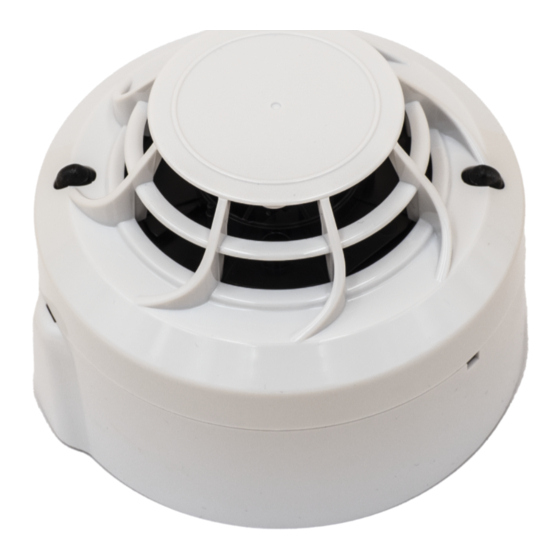
B501RF
32 mm
+
124 g
48 g
(66 g)
Figure 1: B501RF Mounting
≤ M4
Figure 2: Attaching Sensor Head to Base
LINE UP MARK ON
SENSOR HEAD
WITH BULGE ON
BASE AND TURN
CLOCKWISE
Figure 3a: Activation of Tamper Resist Feature
PLASTIC LEVER
Figure 3b: Removing Sensor Head From Base
USE A SMALL-BLADED SCREWDRIVER TO PUSH
PLASTIC IN THE DIRECTION OF THE ARROW
D200-302-00
52051E-RF
WIRELESS THERMAL FIRE SENSOR
INSTALLATION AND MAINTENANCE INSTRUCTIONS
70 mm
=
238 g
50-60 mm
BULGE
MARK ON
SENSOR HEAD
BREAK TAB AT DOTTED LINE BY
TWISTING TOWARDS CENTRE
OF BASE
Pittway Tecnologica S.r.l. Via Caboto 19/3, 34147 TRIESTE, Italy
52051RE-RF
AND
DESCRIPTION
These heat sensors are battery operated RF devices designed for
use with the M200G-RF radio gateway. They contain a wireless
40°C
transceiver and run on an addressable fire system (using a
compatible proprietary communication protocol).
-30°C
The 52051E-RF provides fixed 58
The 52051RE-RF provides 58
temperature sensing (A1R).
The sensors plug into the B501RF wireless base.
These devices conform to EN54-25 and EN54-5 (classes A1S
and A1R). They comply with the requirements of 2014/53/EU for
conformance with the RED directive.
SPECIFICATIONS
Supply Voltage:
Standby Current:
Red LED Current Max: 4mA
Re-sync time:
from device power on)
Batteries:
Battery Life:
Radio Frequency:
RF output power:
Range:
Relative Humidity:
INSTALLATION
This equipment and any associated work must be installed in
accordance with all relevant codes and regulations.
Figure 1 details the installation of the B501RF base.
Spacing between radio system devices must be a minimum of 1m
Figure 2 details attaching the sensor head to the base.
Anti-Tamper Features
The base includes a feature that, when activated, prevents removal
of the sensor from the base without the use of a tool. See Figures
3a and 3b for details on this.
Head Removal Warning - An alert message is signalled to the CIE
via the Gateway when a head is removed from its base.
Figure 4 details the battery installation and the location of the rotary
address switches
Batteries should only be installed at the time of commissioning
Using these battery products for long periods at
temperatures below -20°C can reduce the battery life
Observe the battery manufacturer's precautions for use and
Only use the batteries recommended in this manual and do
not mix batteries from different manufacturers
SETTING THE ADDRESS
Set the loop address by turning the two rotary decade switches
on the underside of the sensor (see figure 4), using a screwdriver
to rotate the wheels to the desired address. The device will take
one sensor address on the loop. Select a number between 01 and
159 (Note: The number of addresses available will be dependent
on panel capability, check the panel documentation for information
on this).
C temperature sensing (A1S).
o
C rate-of-rise (10
o
3.3 V Direct Current max.
@ 3V: 120 µA (typical in normal operating mode)
35s (max time to normal RF communication
4 x Duracell Ultra123 or Panasonic Industrial 123
4 years @ 25
C
o
865-870 MHz
14dBm (max)
500m (typ. in free air)
10% to 93% (non-condensing)
.
Important
Warning
considerably (by up to 30% or more)
requirements for disposal
E N G L I S H
I 56- 3891- 003
C/minute)
o
I56-3891-003
Advertisement
Table of Contents

Related Manuals for System Sensor 52051E-RF


Summary of Contents for System Sensor 52051E-RF
- Page 1 B501RF transceiver and run on an addressable fire system (using a 32 mm compatible proprietary communication protocol). 70 mm -30°C The 52051E-RF provides fixed 58 C temperature sensing (A1S). The 52051RE-RF provides 58 C rate-of-rise (10 C/minute) temperature sensing (A1R).
- Page 2 Heat sensors cannot last forever, and we recommend replacement 0333 16 after 10 years. System Sensor Europe, Life Safety Distribution GmbH Javastrasse 2, 8604 Hegnau, Switzerland 52051E-RF DOP-IRF003 52051RE-RF DOP-IRF004 EN54-25: 2008 / AC: 2010 / AC: 2012 Components Using Radio Links.
-
Page 3: Specifiche Tecniche
70 mm comunicazione proprietario. -30°C Il modello 52051E-RF è un rivelatore di calore con soglia di allarme fissa a 58 C (classe A1S). Il modello 52051RE-RF è un rivelatore di calore termovelocimetrico con una soglia di allarme fissa a 58 C (classe A1R). - Page 4 Dichiarazione di Conformità UE Il fabbricante, Life Safety Distribution GmbH dichiara System Sensor Europe, Life Safety Distribution GmbH che i tipi di apparecchiature radio 52051E-RF e Javastrasse 2, 8604 Hegnau, Switzerland 52051RE-RF sono conformi alla direttiva 2014/53 / EN54-25: 2008 / AC: 2010 / AC: 2012 Componenti che utilizzano collegamenti Il testo completo della Dichiarazione di radio.
-
Page 5: Instalación
B501RF 32 mm (utilizando un protocolo de comunicación compatible). 70 mm El modelo 52051E-RF es un sensor térmico de temperatura fija a 58 -30°C (A1S). El modelo 52051RE-RF es un sensor termovelocimétrico 58 C (10 minuto) (A1R). - Page 6 Declaración EU de conformidad 52051E-RF DOP-IRF003 0333 16 52051RE-RF DOP-IRF004 Por la presente, Life Safety Distribution GmbH declara que los equipos radioeléctrico 52051E-RF y 52051RE-RF System Sensor Europe, Life Safety Distribution GmbH son conformes con la Directiva 2014/53/EU. Javastrasse 2, 8604 Hegnau, Switzerland El texto completo de la declaración UE de conformidad...
-
Page 7: Specifications
Sender/Empfänger und werden über ein adressierbares B501RF Brandmeldesystem betrieben. (mit Einsatz eines kompatiblen, proprietären 70 mm Kommunikationsprotokolls). -30°C Der 52051E-RF verfügt über eine festgelegte 58 C Temperatur-Erfassung (A1S). Der 52051RE-RF ist ein Thermodifferentialmelder (A1R) mit 58 C (10 minute). - Page 8 52051E-RF DOP-IRF003 0333 16 Vereinfachte EU-Konformitätserklärung 52051RE-RF DOP-IRF004 Hiermit erklärt Life Safety Distribution GmbH, dass System Sensor Europe, Life Safety Distribution GmbH die Funkanlagentyp 52051E-RF und 52051RE-RF Javastrasse 2, 8604 Hegnau, Switzerland der Richtlinie 2014/53/EU entsprechen. Der vollständige Text der EU-Konformitätserklärung EN54-25: 2008 / AC: 2010 / AC: 2012 ist unter der folgenden verfügbar:...
- Page 9 (utilisant B501RF 32 mm un protocole de communication propriétaire compatible). 70 mm Le détecteur 52051E-RF détecte une température fixe de 58 C (Classe -30°C A1S). Le détecteur 52051RE-RF détecte une température fixe de 58 C et une vitesse d’augmentation de température de 10...
- Page 10 Life Safety Distribution GmbH déclare Les détecteurs thermiques ne sont pas conçus pour une utilisation que les équipements radioélectrique des types 52051E-RF et 52051RE-RF sont conforment à la indéterminée et nous conseillons de les remplacer au bout de 10 ans. directive 2014/53/EU.
Need help?
Do you have a question about the 52051E-RF and is the answer not in the manual?
Questions and answers