Table of Contents
Advertisement
Quick Links
INSTALLATION AND MAINTENANCE INSTRUCTIONS
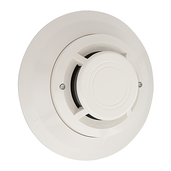
7251 Intelligent Laser Smoke Sensor
Specifications
Operating Voltage Range:
Standby Current:
Max. Alarm Current (LED on:)
Operating Humidity Range:
Operating Temperature Range:
Height:
Diameter:
Weight:
Additional Bases Available:
Before Installing
This sensor must be installed in compliance with the con-
trol panel system installation manual. The installation must
meet the requirements of the Authority Having Jurisdiction
(AHJ). Sensors offer maximum performance when installed
in compliance with the National Fire Protection Association
(NFPA); see NFPA 72.
General Description
Model 7251 is a plug-in type smoke sensor that uses a laser
based sensing chamber. The sensor uses analog-address-
able communications to transmit smoke density and other
information to the control panel. Rotary-decade switches
are provided for setting the sensor's address. Two LEDs on
the sensor are controlled by the panel to indicate sensor
status. An output is provided for connection to an optional
remote LED annunciator (P/N RA400Z).
This detector requires compatible addressable commu-
nications to function properly. Connect this sensor to
listed-compatible control panels only.
Spacing
System Sensor recommends spacing sensors in compliance
with NFPA 72. In low air flow applications with smooth
ceilings, space sensors 30 feet apart. For specific informa-
tion regarding sensor spacing, placement, and special
applications, refer to NFPA 72 or the System Sensor Guide
For Proper Use of System Smoke Detectors, available from
System Sensor (P/N I56-407-XX).
D200-09-00
15 to 32 VDC
330µA @ 24 VDC (one communication every 5 sec. with LED blink enabled)
6.5 mA @ 24 VDC
10% to 93% Relative Humidity, noncondensing
0° to 38°C (32° to 100°F); U.S.
-10° to 50°C (14° to 122°F); Europe
1.7 inches (43 mm) installed in B210LP Base
6.1 inches (155 mm) installed in B210LP Base
4.1 inches (104 mm) installed in B501 Base
5.0 oz. (142 g)
All 200/500 Series bases are compatible.
1
3825 Ohio Avenue, St. Charles, Illinois 60174
Wiring Instructions
All wiring must be installed in compliance with the
National Electrical Code, applicable local codes, and any
special requirements of the Authority Having Jurisdiction.
Proper wire gauges should be used. The installation wires
should be color-coded to limit wiring mistakes and ease
system troubleshooting. Improper connections will prevent
a system from responding properly in the event of a fire.
Remove power from the communication line before
installing sensors.
All wiring must conform to applicable local codes, ordi-
nances, and regulations.
1. Wire the sensor base (supplied separately) per the
wiring diagram, see Figure 1.
2. Set the desired address on the sensor address switches,
see Figure 2.
3. Install the sensor into the sensor base. Push the sensor
into the base while turning it clockwise to secure it in
place.
4. After all sensors have been installed, apply power to the
control unit and activate the communication line.
5. Test the sensor(s) as described in the TESTING section
of this manual.
1-800-SENSOR2, FAX: 630-377-6495
www.systemsensor.com
I56-058-01R
Advertisement
Table of Contents

Related Manuals for System Sensor 7251


Summary of Contents for System Sensor 7251
- Page 1 Improper connections will prevent a system from responding properly in the event of a fire. General Description Model 7251 is a plug-in type smoke sensor that uses a laser Remove power from the communication line before based sensing chamber. The sensor uses analog-address- installing sensors.
- Page 2 Figure 1. Wiring diagram: CAUTION Do not loop wire under terminal 1 or 2. Break REMOTE ANNUNCIATOR wire run to provide supervision of connection. – – – OPTIONAL RETURN LOOP A78-2461-00 B. Smoke Entry: Aerosol Generator (Gemini 501) CAUTION The GEMINI model 501 aerosol generator can be used Dust covers provide limited protection against airborne for smoke entry testing.
- Page 3 Figure 2. Rotary decade address switches: Cleaning It is recommended that the detector be removed from its mounting base to facilitate cleaning. The detector is cleaned as follows: NOTE: Before removing the detector, notify the proper authorities that the smoke detector system is undergoing maintenance and will be temporarily out of service.
- Page 4 Please include a note describing the malfunction and suspected cause of period of three years from date of manufacture. System Sensor makes no failure. The Company shall not be obligated to repair or replace units other express warranty for this smoke detector.
Need help?
Do you have a question about the 7251 and is the answer not in the manual?
Questions and answers