Advertisement
Quick Links
INSTALLATION AND MAINTENANCE INSTRUCTIONS
B200SR-LF-WH, B200SR-LF-IV
Low Frequency Intelligent Sounder Base
SPECIFICATIONS
Base Diameter:
6.875" (17.46 cm)
Base Height (less sensor):
2.0" (5.08 cm)
Weight:
0.6 lb. (272 gm)
Operating Temperature Range:
Refer to applicable sensor Operating Temperature Range using the Base/Sensor Cross Reference Chart at systemsensor.com
Operating Humidity Range:
10% to 93% relative humidity (non-condensing)
External Supply Electrical Ratings
External Supply Voltage:
16 to 33 VDC (VFWR)
Standby Current:
1 mA maximum VDC
Alarm Current:
65 mA maximum @ 33.0 VDC
90 mA maximum @ 24.0 VDC
125 mA maximum @16.0 VDC
SLC Electrical Ratings
SLC Operating Voltage:
15 to 32 VDC
SLC Standby Current:
Refer to applicable sensor specification
Sound Output
Greater than 85 dBA minimum measured in a UL reverberant room at 10 feet, 24 Volts (in continuous tone)
BEFORE INSTALLING
Read System Sensor's Applications Guide for System Smoke Detectors
(SPAG91), which provides detailed information on sensor spacing, placement,
zoning, wiring, and special applications. This manual is available online at
www.systemsensor.com. NFPA 72 and NEMA guidelines should be observed.
The National Fire Alarm Code, NFPA 72, requires effective January 1, 2014,
that audible appliances installed in sleeping areas produce a low frequency
alarm signal that shall be a square wave or provide equivalent awakening abil-
ity with a fundamental frequency of 520 Hz +/– 10%.
NOTICE: This manual should be left with the owner/user of this equipment.
IMPORTANT: The detector used with this base must be tested and maintained
regularly following NFPA 72 requirements. The detector should be cleaned at
least once a year.
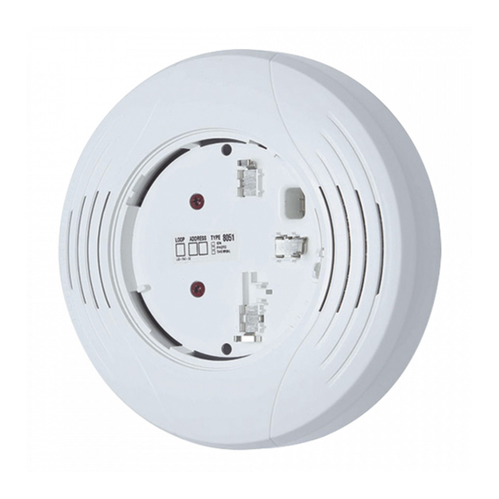
GENERAL DESCRIPTION
The B200SR-LF-WH and B200SR-LF-IV sounder bases are used with address-
able detector heads. For a list of compatible sensors, refer to the System Sensor
website at www.systemsensor.com. Refer to the appropriate manual for more
information on sensors.
The B200SR-LF-WH/B200SR-LF-IV low frequency sounder base generates a
low frequency tone around 520 Hz. Studies have shown that low frequency
audible devices that operate around 520 Hz are more effective in waking in-
dividuals in sleeping areas. It offers maximum flexibility in configuration and
operation to meet or exceed the requirements of UL268 and UL464.
The sounder base is capable of producing either the distinctive three-pulse
temporal pattern (ANSI Temporal 3) fire alarm signal now required by
NFPA 72 for commercial and residential applications or a continuous tone
by simply removing the included jumper from the device. Additionally, the
B200SR-LF-WH/B200SR-LF-IV is designed to be compatible with existing in-
stallations of B501-Series sounder bases.
The sounder base is intended for use with intelligent systems. The sounder
base requires an external 24 VDC power supply. The connections for the
external power supply and the communication loop are isolated to prevent
electrical interaction between them. Refer to the panel manual for maximum
allowable number of units per loop.
NOTE: For NFPA72 Installations, the Temporal 3 tone should be used for public
mode evacuation.
NOTE: When not used as a supplementary evacuation system, the external 24
VDC supply shall be treated as a component of the main power supply system
and shall fall under the requirements of the main power supply system per
NFPA 72.
WIRING GUIDELINES
All wiring must be installed in compliance with the National Electrical Code
and the local codes having jurisdiction and must not be of such length or wire
size which would cause the base to operate outside of its published specifica-
tions. The conductors used to connect smoke sensors to control panels and
accessory devices should be color coded to reduce the likelihood of wiring
errors. Improper connections can prevent a system from responding properly
in the event of a fire.
Wire sizes up to 12 AWG (2.5 mm
base will be shipped with the screw terminals set for 14 AWG wiring. If
12 AWG wire is to be used, back out the screws to allow the wire to fit beneath
the clamping plates. For best system performance, the power (+ and -) wires
and the communication circuit wires should be twisted pair or shielded cable
installed in a separate grounded conduit to protect the communication loop
from electrical interference.
Make wire connections by stripping about
the wire. Then, slide the bare end of the wire under the appropriate clamping
plate (See Figure 1), and tighten the clamping plate screw. Do NOT loop the
wire under the clamping plate. (See Figure 2.) The wiring diagram for a typi-
cal 2-wire intelligent system is shown in Figure 5.
For system monitoring - for terminals 4 and 5, do not use looped wire under termi-
nals. Break wire run as shown in Figure 2 to provide monitoring of connections.
FIGURE 1.
3
4
2
5
1
C0471-08
1
3825 Ohio Avenue, St. Charles, Illinois 60174
1-800-SENSOR2, FAX: 630-377-6495
www.systemsensor.com
2
) may be used with the base. The sounder
3
/
" of insulation from the end of
8
CAUTION
FIGURE 2.
6
I56-4152-005
02/01/2018
C0473-00
Advertisement

Related Manuals for System Sensor B200SR-LF-WH


Summary of Contents for System Sensor B200SR-LF-WH
- Page 1 Make wire connections by stripping about " of insulation from the end of able detector heads. For a list of compatible sensors, refer to the System Sensor the wire. Then, slide the bare end of the wire under the appropriate clamping website at www.systemsensor.com.
- Page 2 MOUNTING TESTING AND MAINTENANCE Mount the B200SR-LF-WH/B200SR-LF-IV mounting plate directly to an electri- Sensors and bases must be tested after installation and as an integral part of cal box. The plate will mount directly to 4" square (with and without plaster a periodic maintenance program.
- Page 3 DETECTOR ACTIVATES SOUNDER BASE(S) - (COMPLIES WITH UL268) UL has approved grouping for up to six B200SR-LF-WH or B200SR-LF-IV low frequency sounder bases. When wired as a group, any detector in the group that has been activated by the panel will cause other B200SR-LF-WH or B200SR-LF-IV units in the group to sound. This type of “local” grouping is accomplished by wiring the grouped devices together using terminal 6, Sounder Base Interconnect, as shown in the diagram.
- Page 4 Please refer to insert for the Limitations of Fire Alarm Systems THREE-YEAR LIMITED WARRANTY System Sensor warrants its enclosed smoke detector base to be free from defects in ma- 12220 Rojas Drive, Suite 700, El Paso TX 79936, USA. Please include a note describing the terials and workmanship under normal use and service for a period of three years from malfunction and suspected cause of failure.
Need help?
Do you have a question about the B200SR-LF-WH and is the answer not in the manual?
Questions and answers