Advertisement
INSTALLATION AND MAINTENANCE INSTRUCTIONS
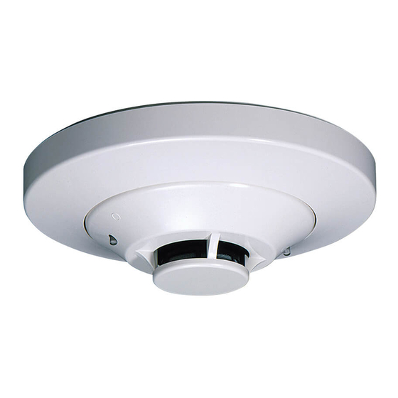
5251RB-WP and 5251B-WP
Weatherproof Intelligent Heat Sensors
SPECIFICATIONS
Diameter:
Height:
Weight:
Installation Temperature Range:
Operating Humidity Range:
Voltage Range:
Standby Current:
LED Current:
Fixed Temperature Rating:
Fixed Temp. & ROR Detection:
Fixed Temp. Detection:
IP Rating:
BEFORE INSTALLING
This sensor must be installed in compliance with the C.I.E. installation manual. The installation must meet the requirements of the Authority Having
Jurisdiction (AHJ). Heat Sensors offer maximum performance when installed in compliance with AS1670.1‐2004.
Please refer to the operators manual for the listed C.I.E. for specific operation and settings for the 5251RB‐WP and 5251B‐WP Heat sensors.
Note:
This detector must be fitted to the special B501A base as supplied with the detector. This detector will not fit into the standard B501 model base.
GENERAL DESCRIPTION
Models 5251RB‐WP and 5251B‐WP are intelligent heat sensors that utilize a state‐of‐the‐art thermistor sensing circuit for fast response. All heat detectors
should be spaced and installed in accordance with the requirements of the relevant authority having jurisdiction and AS1670.1‐2004.
The detector address should be set by handheld programmer (model CP500) from 1 to 159 before installing.
Note: Check C.I.E. maximum loop capacity before setting address higher than 99.
Model 5251RB‐WP is a Type A2R rate‐of‐rise temperature sensor with 63°C fixed temperature alarm setting. Model 5251B‐WP is a Type A2 fixed temperature
heat sensor with 63°C fixed temperature alarm setting.
Two LEDs illuminate red to provide 360° visibility of the sensor alarm indication. The LEDs can be latched on by code command from the C.I.E. for an alarm
indication. The LEDs can also be unlatched to the normal condition by code command. Remote LED annunciator capability is available as an optional accessory
(Part No. RA400Z).
Models 5251RB‐WP and 5251B‐WP require compatible addressable communications to function properly. Therefore these sensors must only be connected to
compatible and listed C.I.E.
WIRING GUIDE
Proper wire gauges should be used. The installation wires should be color coded to limit wiring mistakes and ease system troubleshooting. Improper
connections will prevent a system from responding properly in the event of a fire.
WIRING INSTALLATION GUIDELINES
This detector provides six wires which are divided into three groups,
separately two red, two white and two black wires.
Refer to Figure 1.
Terminal Notes:
Red wire: Power / Loop +ve
Black wire: Power / Loop ‐ve (also Remote LED ‐ve )
White wire: Remote LED +ve
Wiring Diagram refers to Figure 2.
Remove power from the communication line before installing sensors.
1. Secure B501A adapter to the roof or ceiling.
2. Set the sensor to a desired address with handheld programmer.
3. Connect the Wires to loop wiring as per the wiring diagram, see Figure 2A.
4. The wiring connections must be prevent from water, see figure 2B.
5. Install the sensor into the sensor adapter. Push the sensor into the adapter
while turning it clockwise to secure it in place.
6. After all sensors have been installed, apply power to the control unit and
activate the communication line.
7. Test the sensor(s) as described in the TESTING section of this manual.
104 mm (4.1 inches) installed in B501A
51 mm (2.0 inches)
137 g (4.8 ounces)
–20°C to 50°C (‐4°F to 122°F)
10% to 90% Relative Humidity (Non‐condensing)
15 to 32 Volts DC Peak
300 μA @ 24 VDC (one communication every 5 seconds with LED blink enabled)
6.5 mA @ 24 VDC
63°C (146°F)
Type: A2R (5251RB‐WP)
Type: A2 (5251B‐WP)
IP67
1 I56‐2700‐004
www.systemsensor.com
Figure 1.
Advertisement
Table of Contents

Related Manuals for System Sensor 5251RB-WP


Summary of Contents for System Sensor 5251RB-WP
- Page 1 INSTALLATION AND MAINTENANCE INSTRUCTIONS 5251RB-WP and 5251B-WP Weatherproof Intelligent Heat Sensors www.systemsensor.com SPECIFICATIONS Diameter: 104 mm (4.1 inches) installed in B501A Height: 51 mm (2.0 inches) Weight: 137 g (4.8 ounces) Installation Temperature Range: –20°C to 50°C (‐4°F to 122°F) Operating Humidity Range: 10% to 90% Relative Humidity (Non‐condensing) Voltage Range: 15 to 32 Volts DC Peak Standby Current: 300 μA @ 24 VDC (one communication every 5 seconds with LED blink enabled) LED Current: 6.5 mA @ 24 VDC Fixed Temperature Rating: 63°C (146°F) Fixed Temp. & ROR Detection: ...
- Page 2 Figure 2A. Detector Wiring Diagram TAMPER RESISTANT FEATURE The sensor adapter have a tamper‐resistant feature. When this feature is enabled, sensors cannot be removed from the adapter without the use of a small screwdriver or other similar tool. Refer to the sensor adapter installation instruction manual for details in using this feature. TESTING Before testing, notify the proper authorities that the system is undergoing ...
Need help?
Do you have a question about the 5251RB-WP and is the answer not in the manual?
Questions and answers