Table of Contents
Advertisement
Quick Links
INSTALLATION AND MAINTENANCE INSTRUCTIONS
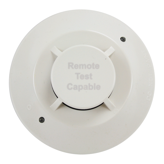
2251BR Intelligent Photoelectric
Smoke Sensor with Remote Test
Capability in Duct Applications
SPECIFICATIONS
Operating Voltage Range:
Standby Current:
Maximum Alarm Current (LED on:)
Operating Humidity Range:
Operating Temperature Range:
Height:
Diameter:
Weight:
Isolator Load Rating:
*Please refer to your isolator base/module manual for isolator calculation instructions.
BEFORE INSTALLING
This sensor must be installed in compliance with the control panel system
installation manual. The installation must meet the requirements of the Au-
thority Having Jurisdiction (AHJ). Sensors offer maximum performance when
installed in compliance with the National Fire Protection Association (NFPA);
see NFPA 72.
GENERAL DESCRIPTION
Model 2251BR is a plug-in type smoke sensors that combines a photoelec-
tronic sensing chamber with addressable-analog communications. The sensor
transmits an analog representation of smoke density over a communication
line to a control panel. Rotary-decade switches are provided for setting the
sensor's address.
Two LEDs on the sensor are controlled by the panel to indicate sensor status.
An output is provided for connection to an optional remote LED annunciator
(P/N RA400Z/RA100Z).
When 2251BR is used in duct applications with a DNR/DNRW, testing can be
done remotely using approved System Sensor test accessories, eliminating the
need for a test coil.
NOTE: Only System Sensor approved accessories may be used with the
2251BR.
The 2251BR requires compatible addressable communications to function
properly. Connect the 2251BR sensor to listed-compatible control panels only.
SPACING
System Sensor recommends spacing sensors in compliance with NFPA 72. In
low air flow applications with smooth ceilings, space sensors 30 feet apart.
For specific information regarding sensor spacing, placement, and special ap-
plications, refer to NFPA 72 or the System Smoke Detector Application Guide,
available from System Sensor.
Duct Applications: 2251BR is listed for use in ducts. See Duct Applications
Guide A05-1004-XX for details on pendant mount applications.
WIRING GUIDE
All wiring must be installed in compliance with the National Electrical Code,
applicable local codes, and any special requirements of the Authority Having
Jurisdiction. Proper wire gauges should be used. The installation wires should
be color-coded to limit wiring mistakes and ease system troubleshooting. Im-
proper connections will prevent a system from responding properly in the
event of a fire.
Remove power from the communication line before installing sensors.
1.
Wire the sensor base (supplied separately) per the wiring diagram, Figure 1.
Set the desired address on the sensor address switches, see Figure 2.
2.
3.
Install the sensor into the sensor base. Push the sensor into the base
while turning it clockwise to secure it in place.
4.
After all sensors have been installed, apply power to the control unit and
activate the communication line.
5.
Test the sensor(s) as described in the TESTING section of this manual.
15 to 32 VDC
300µA @ 24 VDC (one communication every 5 seconds with LED blink enabled)
6.5 mA @ 24 VDC
10% to 93% Relative Humidity, Non-condensing
32°F to 120°F (0°C to 49°C) 2251BR
–4°F to 158°F (–20°C to 70°C) 2251BR in duct applications
2.0˝ (51 mm) installed in B210LP Base
6.1˝ (155 mm) installed in B210LP Base; 4.1˝ (104 mm) installed in B501 Base
5.2 oz. (147 g)
0.0063*
Dust covers provide limited protection against airborne dust particles during
shipping. Dust covers must be removed before the sensors can sense smoke.
Remove sensors prior to heavy remodeling or construction.
FIGURE 1. WIRING DIAGRAM:
REMOTE
ANNUNCIATOR
+
-
(+)
2
1
3
(–)
(–)
CLASS A OPTIONAL WIRING
(+)
Note: Only System Sensor approved accessories may be used with the 2251BR.
FIGURE 2. ROTARY DECADE ADDRESS SWITCHES:
7
8
6
5
4
3
2
1 0
TENS
TAMPER-RESISTANCE
Model 2251BR includes a tamper-resistant capability that prevents its removal
from the bracket without the use of a tool. Refer to the base manual for details
on making use of this capability.
TESTING
Before testing, notify the proper authorities that the system is undergoing
maintenance, and will temporarily be out of service. Disable the system to
prevent unwanted alarms.
All sensors must be tested after installation and periodically thereafter. Testing
methods must satisfy the Authority Having Jurisdiction (AHJ). Sensors offer max-
imum performance when tested and maintained in compliance with NFPA 72.
The sensor can be tested in the following ways:
A.
Functional: Magnet Test (P/N M02-04-01 or M02-09-00)
This sensor can be functionally tested with a test magnet. The test mag-
net electronically simulates smoke in the sensing chamber, testing the
sensor electronics and connections to the control panel.
1. Hold the test magnet in the magnet test area as shown in Figure 3.
2. The sensor should alarm the panel.
3
3825 Ohio Avenue, St. Charles, Illinois 60174
1.800.SENSOR2; Fax: 630.377.6495
www.systemsensor.com
CAUTION
CAUTION: DO NOT LOOP WIRE
UNDER TERMINAL 1 OR 2.
BREAK WIRE RUN TO PROVIDE
SUPERVISION OF CONNECTIONS.
2
1
3
3
7
8
9
6
9
5
4
3
2
1 0
ONES
I56-3534-005R
2
1
C0129-02
C0146-00
04-19
Advertisement
Table of Contents

Related Manuals for System Sensor 2251BR


Summary of Contents for System Sensor 2251BR
- Page 1 Two LEDs on the sensor are controlled by the panel to indicate sensor status. An output is provided for connection to an optional remote LED annunciator (P/N RA400Z/RA100Z). When 2251BR is used in duct applications with a DNR/DNRW, testing can be done remotely using approved System Sensor test accessories, eliminating the (–) need for a test coil.
- Page 2 The Company shall not be obligated to ship under normal use and service for a period of three years from date of manufacture. System Sensor repair or replace units which are found to be defective because of damage, unreasonable use, modifica- makes no other express warranty for this smoke detector.
Need help?
Do you have a question about the 2251BR and is the answer not in the manual?
Questions and answers