Advertisement
Available languages
Available languages
Quick Links
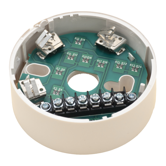
102 mm
1
4
2
3
60 mm
INSTALLATION INSTRUCTIONS FOR B501AP (-IV, -BK) AND
B524HTR INTELLIGENT SENSOR BASES
Before installing bases, please thoroughly read System Sensor's Guide to
Intelligent Fire Systems, which gives information on sensor spacing, placement,
zones and applications. Copies are available from System Sensor at no charge.
GENERAL DESCRIPTION
These bases are designed for use with all System Sensor 500, 200, 200+ and
200 Advanced intelligent ranges of sensors and their variants (Note: If the
B524HTR is used with 200 Advanced Isolator sensors, the isolator feature will not
function. The standard B501AP is white, an IV suffix indicates the base is ivory in
colour, a BK suffix indicates the base is black. Please refer to the control panel
manufacturer for compatibility information.
INSTALLATION
Mounting
The sensor base should be mounted using pan headed screws, with a maximum
diameter of 4mm, and with a maximum head diameter of 8mm. If required,
suitable junction boxes may be used. Standard mounting hole centres are 60mm,
however the B501AP offers from 50mm to 60mm and the B524HTR from 51mm
to 60mm.
The B501AP features knock-outs in the side of the base to allow the access
of surface mounted cabling. Match the markings on the knock-outs to ensure
perpendicular or opposed points (either blank or marked I or II).
Wiring
All wiring should be installed in compliance with local codes and standards, and
the authority having jurisdiction.
The base terminals are designed to accept cables with cross sectional areas
between 0.75mm² and 2.5mm². Reference should always be made to the control
panel specifications for acceptable cable parameters.
Note: To ensure supervision of contacts, the wire run must be broken. Do not loop
the wire under the terminals.
See diagrams opposite for wiring details.
Tamper Resist Feature
B500 bases also include a tamper resist feature, which when activated prevents
removal of the sensor head without the use of a tool.
To activate this feature, break off the tab on the base prior to installing the sensor
(figure 1a). To remove the sensor once this tamper resist is activated, place a
small bladed screwdriver into the slot on the side of the base, push the lever away
from the sensor and rotate the sensor anti clockwise (see figure 1b).
Note: Do not activate the feature if a head removal tool is to be used; this feature
is not reversible without damaging the base.
Figure 1a: Activation of Tamper Resist Feature
Plastic Lever
Figure 1b: Removing Sensor Head From Base
Use a small bladed screwdriver to push
plastic in the direction of the arrow.
REMOTE ANNUNCIATOR OPTION
The RA100Z Remote Annunciator LED is available as an optional accessory. This
unit has a rectangular plate, which fits US single gang light switch boxes.
If a different remote annunciator is to be used, ensure that it is suitably rated for
operation with System Sensor intelligent sensors: 22.5V, 10.8mA at 24VDC supply.
D550-33-00
Pittway Tecnologica S.r.l., Via Caboto 19/3, 34147 Trieste, Italy
B501AP / B524HTR
B501AP (-IV, -BK)
Address Tag
Height
22.5 mm
Weight
39 g
Break tab at dotted line by twisting
towards centre of base
B501AP (-IV, -BK) BASE
If the sensor address needs to be visible without the removal of the sensor head,
break off the address tag from inside the base and place in the slot on the outside
of the base as required.
The tamper resist tab is located in the wall of the base between terminals 2 and 4.
-
+
+
-
Terminal 1:
Loop (-) In and Out and Remote Annunciator (-)
Terminal 4:
Loop (+) Out
Terminal 2:
Loop (+) In
Terminal 3:
Remote Annunciator (+)
B524HTR HEATER BASE
This base contains an anti-condensation heater and is suitable for low temperature
applications.
B524HTR Specifications:
Diameter:
103 mm
Height:
36 mm
Weight:
92 g
Maximum Voltage:
32 V (dc or ac)
Power at 24V:
1.9 W
Maximum permissible peak power: 4W
Equivalent heating resistor value: 300 Ohms
Operating temperature:
-30°C to +60°C
Operating humidity range: 10% to 93% Relative Humidity (Non-condensing)
Tamper Resist Tab
Terminal Strip
(See Table)
Terminal
PCB
Label
1
HTR+
2
HTR-
3
X
4
L+
5
L-
6
LR+
Notes:
1. The B524HTR requires an external power supply to drive the heater resistors
2. Ensure all terminals are fully screwed home prior to installation of the sensor
3. A self adhesive address tag is available for use with the B524HTR, which
is stuck to the side of the base, and labelled as appropriate to allow the
sensor address to be determined without removal of the sensor head
1
Remote Indicator
-
22.5V Nominal
+
4
1
2
3
Connection
HTR+: Heater Power Supply
HTR-: Heater Power Supply
Not Used (Shield)
Loop +
Loop -
Remote Annunciator +
© System Sensor 2009
ENGLISH
Address Tag
I56-2668-002
Advertisement

Related Manuals for System Sensor B501AP-IV


Summary of Contents for System Sensor B501AP-IV
- Page 1 GENERAL DESCRIPTION Terminal 1: Loop (-) In and Out and Remote Annunciator (-) These bases are designed for use with all System Sensor 500, 200, 200+ and 200 Advanced intelligent ranges of sensors and their variants (Note: If the Terminal 4:...
- Page 2 DESCRIZIONE GENERALE Queste basi sono state progettate per l’uso con qualsiasi gamma di sensori intelligenti 500, 200, 200+ e 200 Advanced System Sensor e loro varianti (Nota: In caso di utilizzo del modello B524HTR con sensori dotati di isolamento 200...
- Page 3 INSTRUCCIONES DE INSTALACIÓN DE LAS BASES B501AP (-IV, -BK) Y B524HTR PARA SENSORES INTELIGENTES Antes de instalar las bases, lea atentamente la guía de System Sensor para sistemas analógicos de protección contra incendios que contiene información sobre la distancia, ubicación, tipo de zonas y aplicaciones de los detectores.
- Page 4 B501AP / B524HTR DEUTSCH Falls eine andere Parallelanzeige eingesetzt werden soll ist sicherzustellen, dass diese für den Betrieb in Verbindung mit den System Sensor Analogbrandmeldern geeignet ist: 22,5V; 10,8mA @ 24VDC Versorgungsspannung. B501AP (-IV, -BK) MELDERSOCKEL B501AP (-IV, -BK) 102 mm...
Need help?
Do you have a question about the B501AP-IV and is the answer not in the manual?
Questions and answers