System Sensor B401BH Installation And Maintenance Instructions
Sounder bases
Hide thumbs
Also See for B401BH:
Table of Contents
Advertisement
Quick Links
INSTALLATION AND MAINTENANCE INSTRUCTIONS
B401BH and B401BHA
Sounder Bases
Specifications
Base Diameter:
Base Height (less base and sensor):
Weight:
Operating Temperature Range:
Operating Humidity Range:
Electrical Ratings
Voltage:
Standby Current:
Alarm Current:
Maximum Ripple Voltage:
Start-up Capacitance:
Horn Input Current Requirement:
Sound Output:
Before Installing
Please thoroughly read the System Sensor manual I56-407,
Guide for Proper Use of System Smoke Detectors, which pro-
vides detailed information on detector spacing, placement,
zoning, wiring, and special applications. Copies of this
manual are available at no charge from System Sensor.
NFPA 72 and NEMA should be observed. (For installation
in Canada, refer to CAN/ULC-S524, Standard for the
Installation of Fire Alarm Systems and CEC Part 1, Sec. 32.)
NOTICE: This manual should be left with the owner/user
of this equipment.
IMPORTANT: The detector used with these bases must be
tested and maintained regularly following NFPA 72 require-
ments. The detector used with these bases should be
cleaned at least once a year.
D400-50-00
6 inches (152 mm)
0.75 inches (19mm)
0.3 lb. (140 g)
14° to 140°F (–10° to +60°C)
10% to 95%, noncondensing
17 to 32 VDC
1.0 mA maximum
15 mA maximum
10% of supply voltage
200 µF
600 µA maximum
Greater than 90 dBa measured in anechoic room at 10 feet (3 meters), 24 volts.
85 dBa minimum measured in UL reverberant room.
General Description
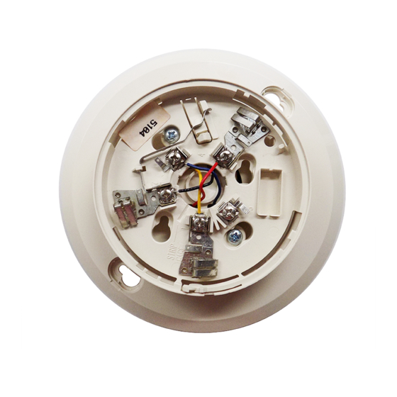
Models B401BH and B401BHA sounder bases are intended
for use with System Sensor 400 Series plug-in sensor heads
in conventional 2-wire plug-in systems. Refer to systems
manuals for the maximum allowable number of units per
loop. The B401BH requires an external 24VDC (nominal)
supply with reverse polarity capability. The connections of
the external supply (terminals 1 and 2) and the initiating
loop (terminals 3, 4, and 5) are isolated in the B401BH to
prevent electrical interaction between them.
When the detector head's visible LEDs are latched on for
approximately 10 seconds, the associated horn sounds. A
loop of horns can be made to sound by reversing the polar-
ity of the external supply.
NOTE: When the associated system is NOT used as a sup-
1
3825 Ohio Avenue, St. Charles, Illinois 60174
1-800-SENSOR2, FAX: 630-377-6495
plementary evacuation system, the external 24VDC
supply must be treated as a component of the main
power supply system with the result that it falls
under the requirements of NFPA 72.
www.systemsensor.com
I56-612-04R
Advertisement
Table of Contents

Related Manuals for System Sensor B401BH


Summary of Contents for System Sensor B401BH
- Page 1 (terminals 1 and 2) and the initiating Installation of Fire Alarm Systems and CEC Part 1, Sec. 32.) loop (terminals 3, 4, and 5) are isolated in the B401BH to prevent electrical interaction between them. NOTICE: This manual should be left with the owner/user of this equipment.
- Page 2 B401BH and B401BHA Terminals Installation Wiring Guidelines Function All wiring must be installed in compliance with the External Supply Positive (+) National Electrical Code and all applicable local codes and External Supply Negative (–) any special requirements of the authority having jurisdic- Negative (–) V in...
- Page 3 Figure 3. Typical wiring layout: Wiring Instructions Figure 4. Mounting to an electrical box: The shorting spring in the base will disengage automatical- ly when the detector head is removed from the base. DO NOT remove the shorting spring since it reengages as the detector head is turned into the base, completing the circuit.
- Page 4 Please refer to insert for the Limitations of Fire Alarm Systems Three-Year Limited Warranty System Sensor warrants its enclosed base to be free from defects in mate- Ohio Avenue, St. Charles, IL 60174. Please include a note describing the rials and workmanship under normal use and service for a period of three malfunction and suspected cause of failure.
Need help?
Do you have a question about the B401BH and is the answer not in the manual?
Questions and answers