
Related Manuals for STIENEN PL-9500


Summary of Contents for STIENEN PL-9500
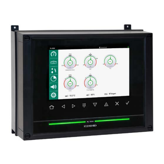
- Page 1 USER MANUAL PL-9500 (-i) POULTRY COMPUTER PL-9500 PL-9500-i © Stienen BE / PL-9500-G-EN02000...
- Page 2 Stienen BE cannot be held liable for any damage, loss or injury resulting from improper use or from use not in accordance with the instructions in this manual.
-
Page 3: Table Of Contents
Contents Page OPERATION Changing language Login Control keys Led bar Terminal number in-/outputs MAIN MENU Overview screen MANAGEMENT Animals Animal weighing Feeding Counters Hour counter Min./Max. Logging CLIMATE House Main ventilation Auxiliary ventilation Heat exchanger Inlet flaps Heating Cooling Temperature controls Miscellaneous FEED Feed weighing... - Page 4 Application notes Animal weighing PL95IAW-N-ENxxxxx Central exhaust PL95ICE-N-ENxxxxx Data communication between poultry computers PL95IDC-N-ENxxxxx Feed system PL95IFS-N-ENxxxxx General description (ventilation controls, temperature control, heating, cooling, humidity) PL95IGD-N-ENxxxxx Heat exchanger PL95IHE-N-ENxxxxx Heating controls PL95IHC-N-ENxxxxx Manure belt PL95IMB-N-ENxxxxx Meteo control PL95IMC-N-ENxxxxx Remote control PL95IRC-N-ENxxxxx Timers PL95ITC-N-ENxxxxx...
-
Page 5: Operation
OPERATION CHANGING LANGUAGE Available languages: ENG CHN JAP Previous Next : select next language (see also “System”, page 30). : select previous language. LOGIN Touch : open login screen. Touch : open numerical keypad. Enter your login code and touch the key. -
Page 6: Led Bar
Alphanumeric: : select other characters. : toggle between lower case letters and capitals. : switch to digits and alternative characters. : decrease/increase setting. : select an option from a selection box. : undo an option/selection in edit mode. : confirm an option/selection in edit mode. : add a breakpoint to/remove a breakpoint from a list (curve, timer). -
Page 7: Terminal Number In-/Outputs
TERMINAL NUMBER IN-/OUTPUTS The terminal number of an input/output consists of the module address, the type of input/output and a 2-digit serial number. Type in-/output Letter Serial number Description 0-10V output 1-99 Analogue output with a range of 0-10V or 10-0V. Relay contact output (this does not include: alarm relay, Relays output 1-99... -
Page 8: Main Menu
MAIN MENU Animals (mutations, reviews, entry data, growth curve, lost) Animal weighing (settings, mutations, history, curve, alarms) Feeding (water/feed, fed, bulked) Management Counters (review, alarms, clear) Hour counter (heating, cooling, external) Min./Max. values (house, outside, sensors) Logging (heat exchanger) House (settings, growth curve, compensations, alarms) Main ventilation (settings, options, growth curve, compensations, alarms) -
Page 9: Overview Screen
OVERVIEW SCREEN Touch “clock”: The corresponding settings screen is opened. ADD MENU ITEM TO FAVOURITES BAR Select the screen that you wish to add to the favourites bar. • Touch the icon of the menu item until the “add” window appears. •... -
Page 10: Management
MANAGEMENT ANIMALS MUTATIONS Enter changes (or 'mutations') (max. 5 classes of mutations): • “Total” column: overview per row, the sum of all mutations (from the last time that animals were entered in the house until today). Some animals have been removed from the house in the meantime: enter •... -
Page 11: Counters
COUNTERS COUNTER Weekly overview per counter: Counter readings per day. • Counter readings per week. • • Total reading (after the last time the counter was cleared). Clear counter reading of the counter shown: Caution! When the counter is cleared the data for today is also deleted. In addition, the overviews of the amounts fed and the... -
Page 12: Climate
CLIMATE HOUSE SETTINGS Set: House temperature. • Day number. • • Put the house into/out of use. Change the house status: always confirm the change separately via the screen below. Confirm GROWTH CURVE Available growth curves: House temperature. • RH compensation. •... -
Page 13: Auxiliary Ventilation
GROWTH CURVE Set growth curve main ventilation. COMPENSATIONS Set influence of RH and CO compensation. ALARMS Switch on/off alarms main ventilation: Temperature alarm. • • Ventilation alarm. AUXILIARY VENTILATION SETTINGS Set: Temperature auxiliary ventilation. • • Bandwidth. Min./Max. ventilation. • Show measurements/calculation of the above parameters. -
Page 14: Inlet Flaps
INLET FLAPS SETTINGS Set parameters, per ventilation group: Control temperature flap (flap on temperature or pressure). • Bandwidth (flap on temperature or pressure). • • Minimum at ventilation (flap on ventilation/tunnel). Maximum at ventilation (flap on ventilation/tunnel). • • Min./Max. ventilation. Show measurements/calculations of the above parameters. -
Page 15: Cooling
COOLING SETTINGS Set parameters per cooling: Temperature at which the cooling controls. • Maximum RH (the cooling switches off when this percentage is exceeded). • Show measurements/calculations of the above parameters. OPTIONS not in use “Soaking” function - only if the house is - (this option is only available with cooling 1, if installed): The cooling is fully energised during the “Period on”... -
Page 16: Temperature Controls
TEMPERATURE CONTROLS SETTINGS Set parameters for the individual controls: Switch the control On/Off. • Temperature at which the temperature control controls. • Display of corresponding temperature measured and calculated. ALARMS Switch temperature control alarm on/off. Set alarm limits (except for a delta T control). View alarm state. -
Page 17: Feed
FEED Touch to open the feeding overview screen: 9,296 Silo contents. • Current silo state (green = current silo, blue = silo blocked, gray = silo empty). • Calculated number of days that feeding from the silo in question is still possible (this •... - Page 18 SILO ASSIGNMENT If more components of the same type are present, you can enter the numbers of the silos containing the same type of component in the search sequence. If a silo is “empty” for any reason (e.g. due to a silo alarm or if the current silo number setting from which the component is to be dosed is 0), the program will automatically look for a silo containing the same type of component.
- Page 19 ALARM FEED SYSTEM The “Alarm” menu option is only shown if the feed weigher is a PFB-35/70. Switching the alarms of the feed weigher on/off: Alarm feed system Deactivate: the main alarm on the PFB feed weigher will also be deactivated (the “alarm” LED on the PFB feed weigher is flashing) Restart weigher If the feed weigher generates an alarm...
-
Page 20: Feed Mixture
FEED MIXTURE MIXTURE Feed mixture Feed timer 3.2.2.2 Component Units Perc. Component 1 Component 2 Component 3 Without growth curve Feed mixture Feed timer 3.2.2.2 Growth curve Component Curve Corr. Perc. Component 1 Component 2 Component 3 With growth curve Note! The values shown in the “Curve”, “Corr.”... -
Page 21: Per Day
PER DAY WATER / FEED Overview of the quantities dosed (feed or water): this includes both the total amount as well as the amount per animal (if animal data is available). Overview Water timer ml/a Today The poultry computer can show the details of the past 7 days. PER PERIOD WATER / FEED Dosage timer: request the amount dosed (water or feed) per animal per period. -
Page 22: Timers
TIMERS MASTER TIMER SETTINGS The master timer is a timer that synchronises the slave timers. Set “slave” instead of “on”: times are related to the master timer (there is still an option of locally correcting the start and end times per timer). Time schedule: •... -
Page 23: Light Timer (Controlled Light)
VARIABLE TIME SCHEDULE NUMBER CORRECTION OF BEGIN AND END TIME (SLAVE MODE) Correct the actual “Begin” and “End” times (last column): enter a correction under the “Begin” and “End” times (first column) (maximum correction + or - 8:00 h). This may be necessary, for example if the master timer is used for several time processes with the same number of periods. -
Page 24: Dosage Timer (Water / Feed / Sequential Timers)
TIME SCHEDULES See “Master timer”. DOSAGE TIMER (WATER / FEED / SEQUENTIAL TIMERS) The timer output of a dosage timer is linked to a counter input. This enables the water and/or feed intake to be limited. If the intake is too low, the controller can generate a “dosage alarm” and stop the dosing of water and/or feed. -
Page 25: Miscellaneous (On/Off Timers, Nest Box Timer)
CURVE Vary the water and/or feed amounts, depending on age, using the curve. TIME SCHEDULES For more extensive information about setting the time schedules: master timer, page 22. PROGRAM “Week program”: set that the dosage timer should not be switched on every day, but, for example, on for 6 days and off for 1 day. -
Page 26: Alarms
ALARMS ALARM STATUS (MAIN ALARM) Switch off main alarm. Display the cause of the alarm and the associated control (and possibly the terminal number or the address). Test (test alarm) Test the operation of the alarm relay (siren): Set Test to “1”... -
Page 27: Alarm Codes
COMMUNICATION Switch the communication alarm on or off. A communication alarm can occur if: • The main station has not received any data from a device that is part of the same RS-485 data communication loop. • Central controls have been installed, but the climate control has not received any data for the central control in question (e.g. - Page 28 (e.g. an incorrectly set feed weighing computer or an incorrect central control number etc.). If the PL-9500 is connected to a feed system: The animal group at the PL-9500 has not been set to communication. • No info from houses You use dosing timers and the “Counter in group”...
- Page 29 Alarm code Description Invalid input The input number does not exist on the module. The times set for a timer must be ascending and the difference between • “Begin” and “End” must be at least 1 minute. The starting time (Begin) + the running time (Propagation time) of a •...
-
Page 30: System
At a flap control; first check if the flap is not in manual operation mode. NOTE! If ALL feed dosing timers work with release contacts, the periods are allowed to overlap. SYSTEM SYSTEM Device: • o Type (158 = PL-9500). o Software version. o Software date. WEC board: • o Software version. -
Page 31: Maintenance And Check Up
MAINTENANCE AND CHECK UP Regular maintenance and checking of the equipment are essential for its proper operation. Don’t forget to clean the ventilation system when cleaning the houses. ● To minimize the energy consumption, it is important that the fans are clean. This also applies to the flaps, measuring fan and the ventilation tube.
Need help?
Do you have a question about the PL-9500 and is the answer not in the manual?
Questions and answers