Mitsubishi Electric LGH-F300RX5-E1 Installation Instructions Manual
Lossnay energy recovery ventilator
Hide thumbs
Also See for LGH-F300RX5-E1:
- Operating instructions manual (9 pages) ,
- Handbook (83 pages)
Advertisement
Quick Links
Lossnay Energy Recovery Ventilator
Models:
LGH-F300RX
-E1, LGH-F470RX
5
Installation Instructions
Models LGH-F300, F470, F600RX
This product needs to be installed properly in order to ensure maximum functionality as well as safety.
Please make sure to read this installation manual before starting the installation.
Installation must be performed in accordance with the requirement of NEC and CEC by authorized personnel only. Please note that improper installation may cause malfunction or accident.
Separate booklet "Operating Instructions" is provided for the customer. The booklet and this manual must be handed over to the customer after completing the installation.
Make sure to follow the instructions "When using the unit in a cold climate below 5°F (-15°C)" when Lossnay is installed in such a case.
Safety precautions
The following signs indicate that death or serious injury may be caused by failure to heed the precautions described below.
Do not modify or disassemble.
Do not
disassemble
The Lossnay unit and remote controller should not be
installed where it is highly humid, like a bathroom, or
other wet place.
(It could cause electric shock or power leakage.)
Prohibition of use in
bath or shower room
Connect the product properly to ground.
(Malfunctioning or power leaks can cause electrical shock.)
Connect the
grounding wire.
Do not place a burning appliance in a place where it is
exposed directly to the air from the Lossnay unit.
(It could cause an accident as a result of incomplete combustion.)
Do not use at a place where it is exposed to high
environment with combustible fumes.
Do not use in an environment such as a chemical factory,
gases, organic solvent fumes, paint fumes, or gases
Prohibited
containing corrosive components are generated.
(It could cause malfunction.)
Do not install this product in a place where it is exposed
to ultraviolet light.
(UV may damage covering insulation.)
When using the product where it is exposed to high temperatures and humidity
moisture is likely to condense in the core, and may result in condensation build
up in the unit. The product should not be used under such conditions.
Outdoor air may enter the Lossnay owing to the pressure difference between
indoor and outdoor or external winds even when the product is not operated. It is
recommended to install an Electrically operated damper to block the outdoor air.
In a cold weather area, an area with strong external winds or where fog occurs frequently,
cold outdoor air, external winds or fog may be introduced into the product when its
operation is stopped. It is recommended to install an electrically operated damper.
-E1, LGH-F600RX
5
-E1
Model LGH-F1200RX
5
WARNING
CAUTION
CAUTION
-E1, LGH-F1200RX
5
(For use by dealer/contractor)
Contents
-E1
5
Safety precautions .........................................................1
Outline drawings ............................................................2
Standard installation examples......................................3
Installation method ........................................................3
Function settings .........................................................12
Trial operation ..............................................................14
Operation when using the unit in a cold climate below 14°F (-10°C) ..16
Check points after installation work .............................16
(It could cause injury if it falls.)
implemented safely and securely in accordance with the engineering
standards and the extension wiring rules for electrical equipment.
Install a power supply isolator at the power supply side as per local
electrical regulations. All supply circuits must be disconnected before
The instructions
connect the cables securely to prevent disconnection when they are pulled.
given must be
followed.
Select an adequate place for the opening to introduce
outdoor air, where it will not intake the exhaust fumes like
combustion gas, or others, and there is no risk of blockage.
A duct made of steel must be installed with care not to be connected
electrically with metals such as metal , wire , stainless steel plate, or others.
Put on gloves during installation. (It could cause injury.)
Make sure the power supply isolator is turned off on the
power distribution panel when Lossnay is not used for a long
period of time after the installation. (It could cause electric
and correctly rated wire / chain hangers. (Use of hardware with
The outside ducts must be tilted at a gradient (1/30 or
more) down toward the outdoor louvres from Lossnay,
and properly insulated. (The entry of rain water may cause
The instructions
given must be
The control box cover must be closed after the installation.
followed.
When connecting external devices (electrically operated damper,
lamp, monitoring unit, etc.) using output signals of the Lossnay
unit, make sure to install safety equipment for the external devices.
When using the product in an environment where there is a window, or opening
near the outdoor louvre , where insects are likely to gather around the interior
or exterior light , take note that small insects may intrude into the product.
unit, where the duct is connected, or other sections, depending on the conditions
of outdoor air and indoor temperature and moisture, even if they are within the
*
1308875HH2502
-E1
5
1
Advertisement

Related Manuals for Mitsubishi Electric LGH-F300RX5-E1


Summary of Contents for Mitsubishi Electric LGH-F300RX5-E1
- Page 1 1308875HH2502 Lossnay Energy Recovery Ventilator Models: LGH-F300RX -E1, LGH-F470RX -E1, LGH-F600RX -E1, LGH-F1200RX Installation Instructions (For use by dealer/contractor) Contents Models LGH-F300, F470, F600RX Model LGH-F1200RX Safety precautions ............1 Outline drawings ............2 Standard installation examples........3 Installation method ............3 Function settings ............12 Trial operation ..............14 Operation when using the unit in a cold climate below 14°F (-10°C) ..16 Check points after installation work ......16...
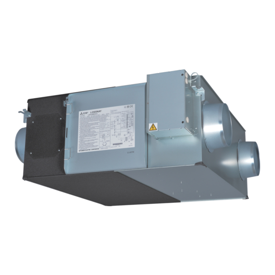
- Page 2 Outline drawings LGH-F300, F470, F600RX Accessory parts *LGH-F470 and F600RX5 types Position where duct direction change is possible (4-9/16” X 13/16” (4-15 X 20) oval) Bypass damper plate ........x16 ....... x4 (4-1/2” X 13/16” (4-13 X 20) oval)* (gray: two wires) ........... x1 (exhaust air outlet) (return air) (outside air intake)
- Page 3 Standard installation examples * Except F1200RX Return air grille Model Distance (not Included) LGH-F300RX 3.3 ft (1 m) or more 8.2 ft (2.5 m) or more LGH- F1200RX 9.8 ft (3 m) or more Lossnay unit The parts can also be installed upside down. Supply air grille (not included) * It can be installed by inverting the top and the bottom.
- Page 4 Installation method (continued) If the suspension bolts are short, change the CAUTION mounting hardware. foreign matter (scraps of paper, vinyl, etc.) has found its way For the models LGH-F470 and F600RX inside the ducts. mounting position. connecting the ducts. been removed to prevent air leakage. where the Lossnay unit is installed will be high during the summer air conditioning season, it is recommended that the indoor duct work be covered with insulation material.
- Page 5 Installation method (continued) When using the unit in a cold climate below 5°F (-15°C) Additional heat insulation is required to use the unit in a place where the outdoor temperature drops below 5°F (-15°C). Do not install the unit upside down, below 5°F (-15°C) outdoor temperature. Be sure to make the additional insulation as below.
- Page 6 Installation method (continued) Model LGH-F1200RX Make sure to attach each sheet of insulation without a gap. CAUTION 1. Make sure to attach each sheet of insulation without a gap. If a gap is found, or the metal surface is exposed, attach additional insulation to cover.
- Page 7 Installation method (continued) After installing the unit, attach additional insulation to the anchor bolts, ceiling suspension 1. Wrap the insulation around the anchor bolts and other parts as shown below. Model LGH-F300RX Models LGH-F470, F600RX Model LGH-F1200RX Ceiling suspension Ceiling suspension Ceiling suspension Insulation Insulation...
- Page 8 Installation method (continued) Wire connection diagram Models LGH-F300, F470, F600RX BROWN 250V HACR Motor for exhaust fan 6.3 A BROWN Motor for supply fan POWER SUPPLY BLACK TAB3 TAB5 250V Capacitor 208-230V~ 60Hz GRAY CN10 6.3 A Motor for Bypass movement YELLOW TAB1 BLUE...
- Page 9 When using the remote/local switching and the ON/OFF input (level signal) Control box cover When connecting to the City Multi, Lossnay remote controller (PZ-52SF-E) or Mitsubishi Electric Air-Conditioner Network System (MELANS). CAUTION When connecting external devices (electrically operated damper, Screw lamp, monitoring unit, etc.) using output signals of the Lossnay...
- Page 10 Installation method (continued) Lossnay External controller input (TM2) (Set to “OFF” at time of shipment.) ) sheathed PVC cable External device Remote controller Lossnay (PZ-60DR-E or PZ- 41SLB-E) Uncharge a-contact Within 457 yd (500 m) External device Power supply CAUTION Power supply Operating switch for external device...
- Page 11 Lossnay When connecting to the City Multi, Lossnay remote controller (PZ-52SF-E) (When CO decreases: Closed) control board or Mitsubishi Electric Air-Conditioner Network System (MELANS) Brown 1 Red 2 CN16 * If centralized control is performed according the wire connection Orange 3 be used.
- Page 12 Installation method (continued) S on the PCB on terminal. When interlocking with Mitsubishi Free Plan air conditioner M-NET transmission cable: Lossnay conditioner conditioner 60DR-E and PZ-52SF-E. M-NET transmission cable controller PZ-60DR-E: PZ-60DR-E Connect to TM4 1 2 on the PCB. (See Section “When connecting with Remote Controller (PZ-60DR-E)”.) PZ-52SF-E:...
- Page 13 Function settings (continued) Settings for pulse input Set as shown when connecting the pulse signal equipment from a building maintenance system to an external input. Mode is given to the “Bypass ventilation”. No pulse input (factory setting) Pulse input Operation Switching to power supply/exhaust when operation starts This sets the fan to run forcibly for 30 minutes when operation starts When the night purge is set by the remote controller PZ-...
- Page 14 Function settings (continued) Exhaust fan stop during defrosting, exhaust fan Low Setting for TM3 67 output Sets the operation of the exhaust fan (when the air supply fan is Operation stopped) during defrosting of the air conditioner when Mr. Slim or City Bypass ventilation operation monitor output.
- Page 15 Trial operation (continued) 2. Stand-alone Lossnay trial operation 3. Complete system trial operation (1) Supply power to the Lossnay unit. Interlock system containing an indoor unit and/or external device (2) Turn the trial operation switch (SW2-1) “On.” ventilation operating. (This will take approximately 1 minute Lossnay are interlocked.
- Page 16 Operation when using the unit in a cold climate below 14°F (-10°C) the outdoor temperature drops below 5°F (-15°C). Make sure to keep the indoor dew point less than 53.6°F (12°C) (indoor condition: malfunctions or dropping water from the unit could occur. Do not use drops below 5°F (-15°C) and indoor dew point is over 41°F (6°C) the unit in such a condition.
- Page 17 Ventilateur Lossnay à récupération d’énergie Modèles: LGH-F300RX -E1. LGH-F470RX -E1. LGH-F600RX -E1. LGH-F1200RX Notice d’installation (destinée au revendeur/à l’entrepreneur) Sommaire Modèles:LGH-F300. F470. F600RX Modèle:LGH-F1200RX Consignes de sécurité ..........17 Schémas d’encombrement ..........18 Exemples d’installations standard ......19 Méthode d’installation ..........19 .........28 ..........30 ...32 Points de contrôle après l'installation ......32 Consignes de sécurité...
- Page 18 Schémas d’encombrement LGH-F300. F470. F600RX Pièces accessoires ........x16 .. x4 ........x1 d’inspection pour l’entretien Dimensions Pas des conduits Diamètre Modèle Poids nominalr 12 2/8 34 1/2 41 7/8 2 9/16 7 7/8 7 9/16 8 3/16 3 1/8 29 3/8 4 7/8 1 3/16 71 lbs 39 1/2...
- Page 19 Exemples d’installations standard Modèle Distance 1 m ou plus 3 m ou plus (bouche Unité installés à l’envers (sens dessus dessous). (bouche d’aspiration * Il peut être monté en inversant le haut et le bas. Espace pour l’entretien d’inspection installé la bride de raccordement du (bouche d’aspiration Unité...
- Page 20 Méthode d’installation (suite) Si les boulons de suspension sont trop courts, ATTENTION ou corps étrangers (bouts de papier, vinyle, etc..) à l’intérieur Pour les modèles LGH-F470 et F600RX des conduits. supérieure. registre à l’intérieur de l’unité Lossnay. l’unité Lossnay est susceptible d’être élevée en été, il est recommandé...
- Page 21 Méthode d’installation (suite) d’isolation sans laisser d’espace. Méthode d’isolation Modèles LGH-F300RX -E1. LGH-F470RX -E1. LGH-F600RX l’isolant pour passer la bride de raccordement des conduits. l’isolant pour passer la bride de raccordement des conduits. ATTENTION Isolation Unité raccordement des conduits d’espace, comme illustré à droite. F300RX F470RX F600RX...
- Page 22 Méthode d’installation (suite) Modèle LGH-F1200RX d’isolation sans laisser d’espace. ATTENTION latérales sans laisser d’espace, comme illustré à droite. Isolation Unité raccordement des conduits B-1, B-2 1 pièce/appareil F1200RX Isolation pièce/appareil Épaisseur 31 1/2 11 1/4 27 9/16 10/16 11 1/4 27 9/16 10/16 5 15/16 (150)
- Page 23 Méthode d’installation (suite) Modèle LGH-F300RX Modèles LGH-F470. F600RX Modèle LGH-F1200RX Isolation Isolation Isolation Isolation Isolation Isolation Isolation Isolation Isolation Isolation Isolation Isolation Travaux électriques Noms des éléments du boîtier de commande Modèles LGH-F300. F470. F600RX Modèles LGH-F1200RX LED4 LED1 LED1 LED4 LED2 LED2...
- Page 24 Méthode d’installation (suite) Schéma de câblage Modèles LGH-F300. F470. F600RX BROWN 250V HACR 6.3 A BROWN BLACK TAB3 TAB5 250V GRAY CN10 6.3 A YELLOW TAB1 BLUE TAB2 MOTEUR DU BLUE ORANGE BULE WHITE MOTEUR DU Câble de transmission et sortie moniteur YELLOW BROWN CN32...
- Page 25 Lors du raccordement à un climatiseur City Multi, à un commutateur de commande de commande à distance Lossnay (PZ-52SF-E) ou au système de réseau de climatiseurs de Mitsubishi Electric (MELANS). ATTENTION lampes, unité de monitorage, etc..) utilisant les signaux de sortie de l’unité...
- Page 26 Méthode d’installation (suite) de section Commutateur distance Décharger le contact a Alimentation externe ATTENTION Alimentation Interrupteur de mise sous tension du avec une télécommande MA. impulsions. côté du câble secteur au bornier d’entrées 1 et 2 9 10 Appareil Mr. Slim (contrôle A ou contrôle Rouge Lossnay...
- Page 27 Lors du raccordement à un climatiseur City Multi, à un commutateur de commande à distance Capteur de CO , etc.. Tableau de Marche/Arrêt Lossnay (PZ-52SF-E) ou au système de réseau de climatiseurs de Mitsubishi Electric (MELANS). Marron 1 Rouge 2 CN16 Orange 3 Jaune 4 Sélection du...
- Page 28 Méthode d’installation (suite) En cas de synchronisation avec un climatiseur à plan libre Mitsubishi Climatiseur Climatiseur Télécommande PZ-60DR-E: 1, 2 la Section Climatiseur Climatiseur PZ-52SF-E: A, B Télécommande En cas de branchement sur PZ-60DR-E et MELANS ATTENTION Unité d’alimentation circuit imprimé. le blindage.
- Page 29 Réglage de la priorité de la ventilation automatique de dérivation Mode purge nocturne. Entrée d’impulsion Fonctionnement Fonctionnement Fonctionnement Passage au mode de ventilation multi Mode Fonctionnement Puissance après l’arrêt de la sortie (TM4 90 télécommande. l'arrêt commandé par la télécommande. Puissance Aspiration Puissance...
- Page 30 Fonctionnement Fonctionnement Démarre la sortie (TM3 67 thermistor de détection de la température de l'air extérieur Arrête la sortie (TM3 67 après l’arrêt de la sortie (TM3 67 Mode Fonctionnement Pas de reprise Arrêt après reprise Reprise l'arrêt commandé par la télécommande. Mode Fonctionnement Temps entretien...
- Page 31 En cas d’utilisation de système MELANS Fonctionnement Remède appuie sur l’interrupteur de mise en marche du commutateur de commande et/ou sur l’interrupteur de mise en inutilisables. transmission. sur l’interrupteur de mise en marche du extérieur n’est pas couplé. commandes extérieures 1 et 2. 1 et 3.
- Page 32 schéma 10 minutes d’arrêt/60 minutes...
Need help?
Do you have a question about the LGH-F300RX5-E1 and is the answer not in the manual?
Questions and answers