Advertisement
Available languages
Available languages
Quick Links
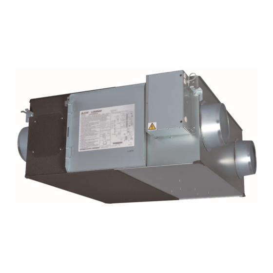
Lossnay Energy Recovery Ventilator
MODELS:
LGH-F300RVX-E, LGH-F470RVX-E, LGH-F600RVX-E
LGH-F1200RVX-E
Installation Instructions
Models LGH-F300 to F600RVX-E
This product needs to be installed properly in order to ensure maximum functionality as well as safety.
Please make sure to read this installation manual before starting the installation.
l Installation must be performed by a dealer or installation contractor. Please note that improper installation may cause malfunction or accident.
"Operating Instructions" and this manual must be handed over to the customer after completing the installation.
Safety precautions
The following signs indicate that death or serious injury may be caused by failure to heed the precautions described below.
WARNING
Do not modify or disassemble.
(It could cause fire, electric shock or injury.)
Do not
disassemble
The Lossnay unit and remote controller should not be
installed where it is highly humid, like a bathroom, or
other wet place.
Prohibition of use in
(It could cause electric shock or power leakage.)
bath or shower room
Connect the product properly to ground.
(Malfunctioning or power leaks can cause electrical shock.)
Connect the
grounding wire.
Use the specified power supply and voltage.
(Use of incorrect power supply or voltage could cause fire
or electric shock.)
Select a place with sufficient strength and install the
main unit securely.
The instructions
given must be
(It could cause injury if it falls.)
followed.
(For use by dealer/contractor)
Model LGH-F1200RVX-E
The instructions
given must be
followed.
Contents
Safety precautions ...............................................1
Outline drawings ..................................................3
Standard installation examples............................4
Installation method ..............................................4
Function settings ...............................................13
Check points after installation work ...................21
Trial operation ....................................................21
Wiring work must be performed by qualified
professionals, and be implemented safely and securely
in accordance with the engineering standards and the
extension wiring rules for electrical equipment.
(Poor connection or improper wiring work could cause
electric shock or fire.)
Install a power supply isolator at the power supply
side as per local electrical regulations. All supply
circuits must be disconnected before obtaining
access to the terminal devices. Use the specified
cable size and connect the cables securely to prevent
disconnection when they are pulled.
(If there is a defect in the connection, there is a possibility
of fire.)
Select an adequate place for the opening to introduce
outdoor air, where it will not intake the exhaust fumes
like combustion gas, or others, and there is no risk of
blockage.
(Shortage of fresh air could put the room in a state of
oxygen deficiency.)
A duct made of steel must be installed with care not
to be connected electrically with metal, wire, stainless
steel plate, or others.
(It could cause fire when power leakage occurs.)
Not suitable for use with solid-state speed controls.
1911876H33301
Eng-1
Advertisement

Related Manuals for Mitsubishi Electric LGH-F300RVX-E


Summary of Contents for Mitsubishi Electric LGH-F300RVX-E
- Page 1 1911876H33301 Lossnay Energy Recovery Ventilator MODELS: LGH-F300RVX-E, LGH-F470RVX-E, LGH-F600RVX-E LGH-F1200RVX-E Installation Instructions (For use by dealer/contractor) Models LGH-F300 to F600RVX-E Model LGH-F1200RVX-E Contents Safety precautions ..........1 Outline drawings ..........3 Standard installation examples......4 Installation method ..........4 Function settings ..........13 Check points after installation work ....21 Trial operation ............21...
- Page 2 Safety precautions (continued) CAUTION Do not place a burning appliance in a place where it is Always use the specified suspension bolts, nuts and exposed directly to the air from the Lossnay unit. washers or correctly rated wire / chain hangers. (It could cause an accident as a result of incomplete combustion.) (Use of hardware with insufficient strength could result in Do not use at a place where it is exposed to high...
- Page 3 34 15/16 13 1/32 34 1/2 41 7/8 3 11/32 7 7/8 7 9/16 8 3/16 3 1/8 29 3/8 5 5/16 4 7/8 1 3/16 LGH-F300RVX-E (888) (1016) (331) (875) (1063) (85) (200) (192) (208) (79) (745) (135.5) (124)
- Page 4 * Except the LGH-F1200 RVX-E. • Duct length Return air grille Model Distance (not Included) LGH-F300RVX-E 3.3 ft (1 m) or more LGH-F470 and F600RVX-E 8.2 ft (2.5 m) or more EA (exhaust air outlet) LGH-F1200RVX-E 9.8 ft (3 m) or more Lossnay unit •...
- Page 5 Installation method (continued) 3. Preparing the anchor bolts 5. Connecting the ducts Mount the washers (outer diameter of >13/16 inch for 3/8-16 UNC (1) Fasten the duct securely to the duct connecting flange, and (21 mm for M10) >15/16 inch for 7/16-14 UNC (24 mm for M12) wrap aluminium tape (field supply) around the joints so that and nuts onto the pre-recessed anchor bolts (3/8-16 or 7/16-14 there is no air leakage.
- Page 6 Installation method (continued) 6. When changing the direction of the out Electrical installation door side duct (EA/OA) ···Except for LGH- With this product, the wiring installation method will vary according to F1200RVX-E the design of the system. Perform electrical installation to meet local electrical regulations. (1) Removal of flange cover * Always use double insulated PVC cable for the transmission cables.
- Page 7 * A power supply isolator must be installed. * Always use an isolator for the main switch power connection. * Select proper circuit breaker according to the electrical current information in the chart below. Model LGH-F300RVX-E LGH-F470RVX-E LGH-F600RVX-E Maximum current when operating [A] 2.05...
- Page 8 Installation method (continued) Wire connection diagram ----- Model LGH-F1200RVX-E * TM1, TM2, TM3, TM4, TB5 shown in dotted lines are field work. * Be sure to connect the ground wire. * A power supply isolator must be installed. * Always use an isolator for the main switch power connection. * Select proper circuit breaker according to the electrical current information in the chart below.
- Page 9 To change fan speed by 0 - 10 VDC input When using the remote/local switching and the ON/OFF input (level signal) When connecting to the City Multi or Mitsubishi Electric Air- Conditioner Network System (MELANS). To start/stop Lossnay stand-alone operation without using the...
- Page 10 Installation method (continued) When interlocked with indoor unit of air conditioner or When the external device has an uncharged a-contact signal other external device including other manufactures • The wiring should be the following picture. AWG 20 (0.5 mm ) to AWG 17 (1.0 mm CAUTION Lossnay external sheathed PVC cable...
- Page 11 Installation method (continued) By-pass monitor or Pre-heater signal output. Operation monitor output By-pass monitor or Pre-heater signal can be selected at SW5-6. Operation monitor output can be selected to sympathize with exhaust (Refer to function settings No. 58 fan or supply fan at SW 5-2. Always check that it is the intended setting.
- Page 12 Installation method (continued) When connecting to the City Multi, Mitsubishi Electric Air- When switching By-pass externally. Conditioner Network System (MELANS) Establish the wire connection by inserting the optional remote display M-NET transmission cable adaptor (PAC-SA88HA-E or PAC-725AD) in the connector CN26 (White).
- Page 13 Pulse input setting (SW6) No. 63 External fan speed input setting (0 - 10 VDC) SW6-1SW6-2SW6-3SW6-4SW7-8 No. 6 Indoor negative pressure setting LGH-F300RVX-E No. 7 Indoor positive pressure setting LGH-F470RVX-E No. 63 External fan speed input setting (0 - 10 VDC) LGH-F600RVX-E No.
- Page 14 Function settings (continued) Setting Data Factory DIP-SW No Function setting Indicator Indicator Indicator N/A Filter maintenance and fan power up setting Dip-SW available available Fan power against filter choking priority Fan power Fan power up N/A up N/A up available 2 Lossnay core maintenance indicator setting Available Stop when...
- Page 15 Function settings (continued) Filter maintenance and fan power up No. 1 No.7 Indoor positive pressure setting setting against filter choking Set the schedule for filter cleaning based on the estimated Supply fan speed becomes bigger Exhaust fan Fan speed Supply concentration of dust in the air.
- Page 16 Function settings (continued) Exhaust fan setting at OA temperature Night-purge setting 1) No.14 No.30 lower than 5 ˚F (-15 ˚C) Air volume Sets the operation of the exhaust fan when the outdoor air is lower Set fan speed during Night-purge. To use Night-purge function, it is than 5 ˚F (-15 ˚C) (when supply fan stop).
- Page 17 Function settings (continued) No.36 No.41 Outdoor temperature display setting Outdoor temperature correction Set to display outdoor temperature detected by Lossnay unit Set the correction for the outdoor temperature displayed on the thermistor or not. PZ-61DR-E screen by function No. 36 This function is N/A from Lossnay unit DIP-SW.
- Page 18 Function settings (continued) Note; Automatic ventilation mode setting 3) No.54 The ventilation mode follows the table below. The lowest indoor temperature setting Interlocked air conditioner Remote controller Lossnay Set one of conditions for By-pass mode in auto ventilation operation, (Mr. Slim or City Multi) minimum indoor temperature.
- Page 19 Function settings (continued) Example 2 Operation monitor output synchronized No.57 By-pass/Energy recovery ventilation map in automatic ventilation with exhaust fan or supply fan mode Set operation monitor output from TM3 90 synchronized with 104(40) supply of exhaust fan. 101(38) Energy recovery ventilation area Also supply fan delay operation, ex.
- Page 20 Function settings (continued) Pre-heater output setting 1) No.59 No.63 External fan speed input setting (0 - 10 VDC) ON temperature Set the outdoor temperature for Pre-heater output ON. Set external fan speed input setting. When detecting temp. becomes the setting or less, Pre-heater output DIP-SW PZ-61DR-E Setting...
- Page 21 Check points after installation work After installation work, please double-check the points below. If there is any trouble, it must be done correctly. (1) Check points - Unit installation Is the insulation wrapped around the outside ducts? [Refer to Installing the Lossnay unit] page 5 Is the outside ducts installed correctly? [Refer to Installation example]...
- Page 22 Trial operation (continued) 4. If trouble occurs during trial operation Symptom Remedy Will not operate even when the • Check the power supply. (The specified power supply is single-phase 208-230 V 60 Hz) operation switch for the remote • Check for a short circuit or disconnection in the transmission cable. (Check that the voltage between controller (PZ-61DR-E) is pressed.
-
Page 23: Table Of Contents
Ventilateur Lossnay à récupération d’énergie MODÈLES : LGH-F300RVX-E, LGH-F470RVX-E, LGH-F600RVX-E LGH-F1200RVX-E Notice d’installation (destinée au revendeur/à l’entrepreneur) Modèles LGH-F300 à F600RVX-E Modèle LGH-F1200RVX-E Sommaire Consignes de sécurité .........1 Schémas d’encombrement ........3 Exemples d’installations standard .......4 Méthode d’installation ..........4 Configuration des fonctions .......13 Points à... - Page 24 Consignes de sécurité (suite) ATTENTION Ne placez pas d’appareil de chauffage dans un endroit directement exposé au souffle produit par l’unité Lossnay. (La combustion incomplète pourrait provoquer un accident.) Les conduits extérieurs doivent être inclinés (1/30 ou plus) vers le bas vers les grilles extérieures de l’unité N’utilisez pas l’appareil dans un endroit exposé...
-
Page 25: Schémas D'encombrement
34 15/16 13 1/32 34 1/2 41 7/8 3 11/32 7 7/8 7 9/16 8 3/16 3 1/8 29 3/8 5 5/16 4 7/8 1 3/16 LGH-F300RVX-E (888) (1016) (331) (875) (1063) (85) (200) (192) (208) (79) (745) (135.5) (124) -
Page 26: Exemples D'installations Standard
* Sauf les LGH-F1200RVX-E. • Longueur de conduit Modèle Distance Grille de reprise d’air (non fournie) LGH-F300RVX-E 3,3 ft (1 m) ou plus LGH-F470 et F600RVX-E 8,2 ft (2,5 m) ou plus LGH-F1200RVX-E 9,8 ft (3 m) ou plus EA (bouche d’évacuation d’air) - Page 27 Méthode d’installation (suite) 3. Préparation des boulons d’ancrage 5. Raccordement des conduits Installez les rondelles (diamètre extérieur >13/16 pouces pour 3/8-16 UNC (1) Fixez solidement le conduit sur la bride de raccordement du conduit et (21 mm pour les boulons M10), >15/16 pouces pour 7/16-14 UNC (24 pour enroulez du ruban en aluminium (fourni sur site) autour des joints pour les boulons M12) et les écrous sur les boulons d’ancrage (3/8-16 ou 7/16-14 éviter toute fuite d’air.
- Page 28 Méthode d’installation (suite) 6. Lors du changement de sens du conduit côté Travaux électriques extérieur (EA/OA) sauf pour les Modèle LGH- Sur cet appareil, la méthode de câblage diffère selon la conception du système. F1200RVX-E L’installation électrique doit être conforme aux règlements locaux sur les installations électriques.
- Page 29 * Un sectionneur électrique doit être installé. * Utilisez toujours un sectionneur pour la connexion d’alimentation de l’interrupteur principal. * Sélectionnez un coupe-circuit approprié selon les informations de courant électrique dans le tableau ci-dessous. Modèle LGH-F300RVX-E LGH-F470RVX-E LGH-F600RVX-E Intensité maximale lors du...
- Page 30 Méthode d’installation (suite) Schéma de câblage ----- Modèle LGH-F1200 RVX-E * TM1, TM2, TM3, TM4, TB5 représentés par les lignes pointillées correspondent au travail sur site. * Veillez à raccorder le fil de terre. * Un sectionneur électrique doit être installé. * Utilisez toujours un sectionneur pour la connexion d’alimentation de l’interrupteur principal.
- Page 31 ARRÊT (signal de niveau) de commande a Lors du raccordement à un climatiseur City Multi ou au système de réseau de climatiseurs de Mitsubishi Electric (MELANS). b Pour démarrer/arrêter le fonctionnement indépendant de l’unité Lossnay sans le contrôleur à distance ATTENTION •...
- Page 32 Méthode d’installation (suite) Lorsque l’appareil externe présente un signal de contact a non chargé Lorsque l’appareil est couplé avec l’unité intérieure du climatiseur ou un autre appareil externe y compris ceux d’autres fabricants • Le câblage doit être effectué comme illustré ci-dessous. ATTENTION Câble gainé...
- Page 33 Méthode d’installation (suite) Sortie du signal du moniteur de dérivation ou du Sortie du moniteur de fonctionnement préchauffage. Le signal du moniteur de dérivation ou du préchauffage peut être sélectionné à La sortie du moniteur de fonctionnement peut être sélectionnée pour s’accorder SW5-6.
- Page 34 Lors du raccordement à un climatiseur City Multi, au système Lors du passage à la dérivation, commandé de l’extérieur. de réseau de climatiseurs de Mitsubishi Electric (MELANS) Établissez la connexion en enfilant l’adaptateur d’affichage à distance en option Câble de transmission M-NET (PAC-SA88HA-E ou PAC-725AD) dans le connecteur CN26 (blanc).
-
Page 35: Configuration Des Fonctions
* Toutes les fonctions, à l’exception des fonctions « Essai de fonctionnement » SW6-1 SW6-2 SW6-3 SW6-4 SW7-8 et « Réglage de l’unité principale », peuvent également être configurées LGH-F300RVX-E à partir du contrôleur à distance (PZ-61DR-E).Si vous activez ensuite LGH-F470RVX-E la fonction à... - Page 36 Configuration des fonctions (suite) N° de Données de réglage Configura- N° Fonction commutateur tion d’usine Indicateur Indicateur Indicateur N/A disponible disponible Augmenta- Priorité com- Augmenta- Augmenta- Réglage de l’entretien du filtre et de l’augmentation de la tion de la mutateur tion de la tion de la puissance du ventilateur contre l’encrassement du filtre...
- Page 37 Configuration des fonctions (suite) Réglage de l’entretien du filtre et de l’augmentation de la N° 1 N° 7 Réglage de la pression positive intérieure puissance du ventilateur contre l’encrassement du filtre Programmez le nettoyage du filtre en fonction de l’estimation de la La vitesse du ventilateur d’alimentation Ventilateur d’évacuation Affichage de...
- Page 38 Configuration des fonctions (suite) Réglage du ventilateur d’évacuation avec Réglage de l’évacuation de nuit 1) N° 14 N° 30 une température OA inférieure à 5 ˚F (-15 ˚C) Volume d’air Définit le fonctionnement du ventilateur d’évacuation lorsque l’air extérieur est Réglez la vitesse du ventilateur pendant l’évacuation de nuit.
- Page 39 Configuration des fonctions (suite) Réglage de l’affichage de la température N° 36 N° 41 Correction de la température extérieure extérieure Réglez pour afficher ou non la température extérieure détectée par le Réglez la correction de la température extérieure affichée sur thermistor de l’unité...
- Page 40 Configuration des fonctions (suite) Remarque : Réglage du mode de ventilation automatique 3) N° 54 Le mode de ventilation est comme indiqué dans le tableau ci-dessous. Réglage de la température intérieure la plus basse Climatiseurs synchronisés (Mr. Contrôleur à distance Lossnay Slim ou City Multi) Réglez une des conditions pour le mode de dérivation lors du fonctionnement...
- Page 41 Configuration des fonctions (suite) Exemple 2 Sortie du moniteur de fonctionnement synchronisée avec N° 57 Graphique de ventilation de dérivation/à récupération d’énergie en mode le ventilateur d’évacuation ou le ventilateur d’alimentation de ventilation automatique 104(40) Réglez la sortie du moniteur de fonctionnement de TM3 90 synchronisée avec le ventilateur d’alimentation ou d’évacuation.
- Page 42 Configuration des fonctions (suite) Réglage de la sortie du préchauffage 1) Réglage d’entrée de la vitesse du ventilateur N° 59 N° 63 externe (0 - 10 VCC) Température activée Activez la température extérieure de la sortie du préchauffage. Définissez le réglage d’entrée de la vitesse du ventilateur externe. Lorsque la température détectée devient celle du réglage ou inférieure à...
-
Page 43: Points À Vérifier Après Les Travaux D'installation
Points à vérifier après les travaux d’installation Après les travaux d’installation, vérifiez les points ci-dessous. En cas de problème, effectuez correctement. (1) Points à vérifier - Installation de l’unité Du matériau isolant est-il enroulé autour des conduits extérieurs ? [Reportez-vous à la section Installation de l’unité Lossnay] page 5 Les conduits extérieurs sont-ils installés correctement ? [Reportez-vous à... - Page 44 Essai de fonctionnement (suite) 4. En cas de problème pendant l’essai de fonctionnement Symptôme Remède Ne fonctionne pas même lorsqu’on • Vérifiez l’alimentation électrique. (L’alimentation spécifiée est monophasée 208-230 V 60 Hz.) appuie sur l’interrupteur d’alimentation • Vérifiez l’absence de court-circuit ou de déconnexion au niveau du câble de transmission. (Vérifiez que la tension du contrôleur à...
Need help?
Do you have a question about the LGH-F300RVX-E and is the answer not in the manual?
Questions and answers