Mitsubishi Electric LGH-F940RVXT2-E Installation Instructions Manual
Lossnay energy recovery ventilator, for use by dealer/contractor
Hide thumbs
Also See for LGH-F940RVXT2-E:
- Handbook (106 pages) ,
- Operating instructions manual (6 pages)
Table of Contents
Advertisement
Quick Links
Lossnay Energy Recovery Ventilator
MODELS:
LGH-F940RVXT2-E
LGH-F1200RVXT2-E
LGH-F1500RVXT2-E
Installation Instructions
This product needs to be installed properly in order to ensure maximum functionality as well as safety.
Please make sure to read this installation manual before starting the installation.
l Installation must be performed by a dealer or installation contractor. Please note that improper installation may cause malfunction or accident.
"Operating Instructions" and this manual must be handed over to the customer after completing the installation.
For use by dealer/contractor
Contents
1. Safety precautions ..........................................................2
2. Outline drawings .............................................................5
3. Before installation ...........................................................5
4. Standard installation examples.......................................6
5. Installation method .........................................................7
5.1 Installing the Lossnay unit .........................................7
5.2 Electrical installation..................................................9
6. Function settings ..........................................................20
7. Check points after installation work ..............................36
8. Trial operation...............................................................37
8.2 Lossnay trial operation ............................................37
8.3 Lossnay trial operation in a whole system ..............37
8.4 If trouble occurs during trial operation .....................38
Eng-1
2406876HG9501
Advertisement
Table of Contents

Related Manuals for Mitsubishi Electric LGH-F940RVXT2-E


Summary of Contents for Mitsubishi Electric LGH-F940RVXT2-E
-
Page 1: Table Of Contents
2406876HG9501 Lossnay Energy Recovery Ventilator MODELS: LGH-F940RVXT2-E LGH-F1200RVXT2-E LGH-F1500RVXT2-E Installation Instructions For use by dealer/contractor Contents 1. Safety precautions ............2 2. Outline drawings .............5 3. Before installation ............5 4. Standard installation examples........6 5. Installation method ............7 5.1 Installing the Lossnay unit .........7 5.2 Electrical installation..........9... -
Page 2: Safety Precautions
2406876HG9501 1. Safety precautions The following signs indicate that death or serious injury may be caused by failure to heed the precautions described below. WARNING Incorrect handling could cause serious injury or death. Do not modify or disassemble. It could cause fire, electric shock or injury. Do not disassemble The Lossnay unit and remote controller should not be installed where it is highly humid, like a bathroom, or other wet place. - Page 3 2406876HG9501 CAUTION Incorrect handling could cause injury or damage to property or household effects. Do not place a burning appliance in a place where it is exposed directly to the air from the Lossnay unit. It could cause an accident as a result of incomplete combustion. Do not use at a place where it is exposed to high temperatures (104 ˚F (40 ˚C) or higher), naked flames, or in environment with combustible fumes.
-
Page 4: Bypass Operation
2406876HG9501 Bypass operation LGH-FRVXT2-E series does not have bypass damper. Bypass operation of LGH-FRVXT2-E series is realized by only one fan motor operation from 2 fan motors in supply and exhaust path. Air path to 2 fan motors in each supply and exhaust are separated physically after the heat exchange core. This structure contribute that one fan motor operation in each supply and exhaust path makes less-energy recovery operation possible. -
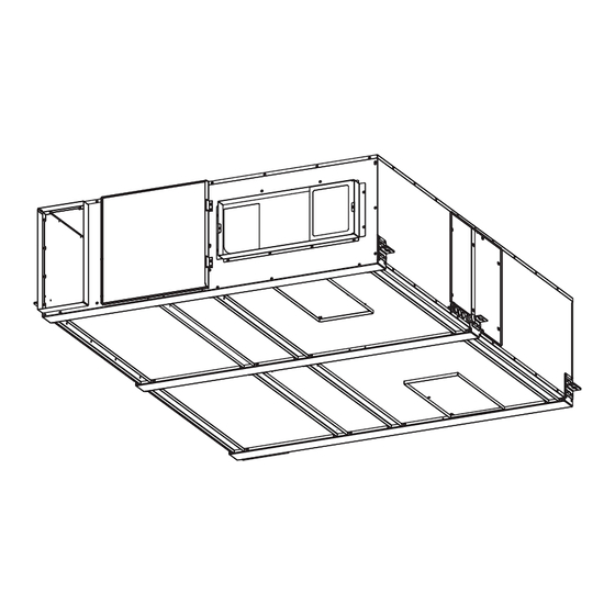
Page 5: Outline Drawings
2406876HG9501 2. Outline drawings LGH-F940RVXT2-E, LGH-F1200RVXT2-E, LGH-F1500RVXT2-E 43/64 (17) 18 5/16 (465) 18 5/16 (465) 43/64 (17) Ceiling suspension fixture Lossnay cores (6-15 X 30 oval) Flange 37 19/32 (955) 37 19/32 (955) Flange ) air filters ) air filters... -
Page 6: Standard Installation Examples
2406876HG9501 4. Standard installation examples LR switching is OFF (Factory setting) Unit: Inch (mm) 3.3 yd (3 m) or more Filter and core maintenance opening (recommended) 23 5/8 (600) x 23 5/8 (600) Return air grille (outside air intake) (not included) Lossnay unit Supply air grille (exhaust air outlet) -
Page 7: Installation Method
2406876HG9501 5. Installation method 5.1 Installing the Lossnay unit 5.1.3 Mounting Lossnay unit (1) Hang the ceiling suspension fixtures on the anchor bolts and adjust 5.1.1 Determination of air path in such a way that Lossnay unit is leveled with in ± 0.5°. (2) Tighten up securely using double nuts. - Page 8 2406876HG9501 * This picture shows the air path of factory setting. In case LR switch- ing is enabled, the path becomes opposite. Inlet flange 18 5/16 x 8 21/32 (465 x 220) Outdoor side Room side Outlet flange 9 27/32 x 25 19/32 (250 x 650) Unit: Inch (mm) CAUTION •...
-
Page 9: Electrical Installation
2406876HG9501 5.2 Electrical installation With this product, the wiring installation method will vary according to the design of the system. Perform electrical installation to meet local electrical regulations. * Always use double insulated cable for the transmission cables. * Wiring work must be performed by qualified professionals. * All supply circuits is disconnected and all LED on the circuit board shall be lit off, before accessing to the terminal devices. - Page 10 * Always use an isolator for the main switch power connection. * Select proper circuit breaker according to the electrical current information in the chart below. * Do not disconnect connectors while power supplied. Maximum current (A) Maximum input 208-240 V Three phase 60Hz LGH-F940RVXT2-E 2.3-2.0 2.3-2.0 3.2-2.8 LGH-F1200RVXT2-E 3.4-3.0 3.4-3.0...
- Page 11 2406876HG9501 5.2.3 Connecting the power supply cable (1) Loosen the black screws. Control cover can remove without removing screws. Black screws Control cover (2) Connecting the power supply cable and transmission cable. Pass the Power supply cable through the bush* and connect to the TM1 terminal block using the round terminals.
- Page 12 • Take care not to connect the power supply cable or M-NET transmission cable. 9 When connecting to the City Multi, Mitsubishi Electric Air-Condition- er Network System (MELANS) • When connecting multiple cables to the terminal, use round terminal.
- Page 13 2406876HG9501 When interlocked with indoor unit of air conditioner or [SW2-2] setting vary depending on the types of output signal of other external device including other manufactures external device. CAUTION When the external device has a charged operating signal of 12 VDC or 24 VDC •...
- Page 14 2406876HG9501 When operating multiple Lossnay units Signal output from Lossnay unit In the case that Lossnay units are LGH-FRVX2-E and LGH-FRVXT2- Set DIP-SW or Function setting on PZ-62DR-EA as following table E series with PZ-62DR-EA, up to 15 multiple units can be operated at depending on the necessary output signal from Lossnay unit.
- Page 15 2406876HG9501 When using After-heater output signal, the wiring should be as shown When switching fan speed externally by the following picture. (when a sensor or other equipment is connected) Using a field supply sensor, etc., make connection by inserting the Power Supply Power Supply optional remote controller adapter (PAC-SA88HA-E or PAC-725AD) in...
- Page 16 2406876HG9501 When connecting to the City Multi, Mitsubishi Electric Air- To change fan speed by 0 - 10 VDC input Conditioner Network System (MELANS) Establish the wire connection by inserting the optional remote CAUTION controller adapter (PAC-SA88HA-E or PAC-725AD) in the connector TM4, TB5 CN26.
- Page 17 L1L2 L3 2406876HG9501 To start/stop Lossnay stand-alone operation without using the remote control Lossnay external control input Switch Start/stop the unit by a switch connected to TM2 Y Z. When turned the unit ON, it operates at fan speed 4 and automatic ventilation mode without any other external input.
- Page 18 2406876HG9501 Control via Wi-Fi interface or MELCOBEMS MINI Connect the lead wire of a Wi-Fi interface or MELCOBEMS MINI to CN105 on circuit board of Lossnay unit. Regarding the model name of the connectable Wi-Fi interface or MELCOBEMS MINI, please contact the sales company in your market.
- Page 19 • Connect the power supply cable to each Lossnay unit. CAUTION • Only same model can use this function. For example, not avail- Follower unit able between LGH-F940RVXT2-E and LGH-F1200RVXT2-E, or LGH-F1200RVXT2-E and LGH-F1200RVX2-E. • PZ-62DR-EA is mandatory to use this function. (PZ-43SMF-E cannot be used.) Leader unit •...
-
Page 20: Function Settings
Trial operation (SW6) No. 28 Pulse input setting SW6-1 SW6-2 SW6-3 SW6-4 SW6-5 SW6-6 No. 9 Delay start setting for air conditioner starting LGH-F940RVXT2-E No. 6 Indoor negative pressure setting No. 7 Indoor positive pressure setting LGH-F1200RVXT2-E No. 64 Fan speed for air volume “High” setting LGH-F1500RVXT2-E No. - Page 21 2406876HG9501 Setting Data Factory DIP-SW No Function setting Indicator Indicator Indicator Indicator Filter maintenance and fan available available power up setting against filter — — — — — — — — — — — — — choking power up power up power up power up available...
- Page 22 2406876HG9501 Setting Data Factory DIP-SW No Function setting Constant pressure control setting 3) Target voltage for SA - Ones deci- 0.0 V 0.1 V 0.2 V 0.3 V 0.4 V 0.5 V 0.6 V 0.7 V 0.8 V 0.9 V — —...
- Page 23 2406876HG9501 A, B, C DIP-SW only function Filter maintenance and fan power up setting No. 1 against filter choking Auto fan speed setting without Lossnay remote controller or M-NET system controller Set the schedule for filter cleaning based on the estimated concentration of dust in the air.
- Page 24 2406876HG9501 No. 6 No. 12-16 Indoor negative pressure setting Monitor output setting Exhaust fan speed becomes bigger Set operation monitor output from TM3 90 synchronized with fan Supply fan Fan speed Exhaust than supply fan speed. operation, ventilation mode or occurrence of malfunction. Display 1 down 2 down Remote controller indicates fan...
- Page 25 2406876HG9501 Exhaust fan setting during air conditioner No. 17 No. 28 Pulse input setting defrosting This function can be used under the condition Lossnay supply duct is Set external input signal type from external device for TM2. connected to Mr. Slim or City Multi indoor unit. DIP-SW PZ-62DR-EA Setting...
- Page 26 2406876HG9501 Night purge setting 3) Maximum air flow setting in bypass No. 32 No. 35 The lowest outdoor temperature operation Set one of conditions for Night purge start, maximum outdoor When setting the bypass ventilation mode or auto ventilation mode via temperature within 72 hours.
- Page 27 2406876HG9501 No. 38 No. 42 concentration display setting Outdoor temperature correction Set to display CO concentration when the CO sensor is used. Set the correction for the outdoor temperature displayed on the This function is N/A from Lossnay unit DIP-SW. PZ-62DR-EA screen by function No.
- Page 28 2406876HG9501 DIP-SW PZ-62DR-EA Setting Setting Target voltage decimal for No. 45 Supply fan monitor threshold check check SA - Ones decimal place SW No. Setting Function No. Setting Data 0.0 V – – The threshold fan speed of supply fan monitor output can be selected. (Factory setting) –...
- Page 29 2406876HG9501 Example 1 Automatic ventilation mode setting 2) No. 53 Bypass/Energy recovery ventilation map in automatic ventilation The lowest outdoor temperature mode Set one of conditions for Bypass mode in auto ventilation operation, 104(40) minimum outdoor temperature which comes in indoor directly. Energy recovery ventilation area 101(38) This function is N/A from Lossnay unit DIP-SW.
- Page 30 2406876HG9501 Pre-heater output setting 1) No. 60 No. 64 Fan speed for air volume “High” input ON temperature Set the outdoor temperature for Pre-heater output ON. Set the fan speed setting when receiving “High” signal from remote When detecting temp. becomes the setting or less, Pre-heater output controllers (e.g.
- Page 31 2406876HG9501 [Pattern Z] DIP-SW PZ-62DR-EA Setting Setting 0-10 VDC external input Lossnay changes fan speed as the table below. (Connection example: check check fan control SW No. Setting Function No. Setting Data BMS (Building Management System)) [Orange 3 and Green 5 of PAC-SA88HA-E (CN26)] Fan speed changing from Input voltage[VDC]...
- Page 32 - When installing the centralized management devices (including the system controller) in Mitsubishi Electric Air-Conditioner Network System (MELANS), perform emergency stop by the centralized management devices. In this case, do not use the function No. 69...
- Page 33 2406876HG9501 No. 73-78, 87, 88 Air flow Adjust the output of the fan speed. This function can also be set on the Air flow settings screen of the PZ-62DR-EA. This function is N/A from Lossnay unit DIP-SW. PZ-62DR-EA PZ-62DR-EA PZ-62DR-EA Setting Setting Setting...
- Page 34 2406876HG9501 No. 83, 84 No. 89, 90 Filter maintenance interval setting sensor setting - maximum side Filter cleaning sign is displayed on the remote controller according to It is possible to set the CO concentration which fan speed turn into 4. the set interval in this function.
- Page 35 2406876HG9501 No. 93 No. 100 sensor correction Initialization (No.1~99) concentration can be corrected when CO sensor is connected. Set to initialize the remote PZ-62DR-EA setting. In this function, the control value of CO level is corrected. All settings which are changed by users are cancelled. On the other hand, changes the displayed CO level only.
-
Page 36: Check Points After Installation Work
2406876HG9501 7. Check points after installation work After installation work has been completed, check the following points once again. If any failure is detected, be sure to fix it. Check the following points before trial operation, and place a check mark in the corresponding check box. -
Page 37: Trial Operation
• When delay start time is set (when City Multi or Mr. Slim that is connected using a Slim-Lossnay interlocking cable starts operating), check Lossnay operation after the delay start time has passed. 8.3.2 For MELANS system • Check Lossnay operation by using the Mitsubishi Electric Air-Conditioner Network System (MELANS). Eng-37... -
Page 38: If Trouble Occurs During Trial Operation
2406876HG9501 8.4 If trouble occurs during trial operation Symptom Remedy Lossnay does not operate • Check the power supply voltage and connection rightness. (The specified power supply is Three-phase 208-240 even when the operation V 60 Hz) switch of the remote •...
Need help?
Do you have a question about the LGH-F940RVXT2-E and is the answer not in the manual?
Questions and answers