Mitsubishi Electric Lossnay LGH-F300RX3-E Installation Instructions Manual
Hide thumbs
Also See for Lossnay LGH-F300RX3-E:
- Operating instructions (4 pages) ,
- Handbook (41 pages)
Advertisement
Quick Links
Lossnay
Models:
LGH-F300RX
-E
3
LGH-F470RX
-E
3
LGH-F600RX
-E
3
LGH-F1200RX
Installation Instructions
Models LGH-F300, F470, F600RX
Please take the time to read through these instructions before commencing with the installation work. They will
help to install the Lossnay properly and safely.
The separate Operating Instructions are for the user. Make sure that they are handed over to the
customer.
Safety precautions
WARNING
G This product must not be disassembled under any cir-
cumstances. Only authorized repair technicians are
No
qualified to conduct disassembly and repairs.
disassembly
(Failure to heed this warning may result in fire, electrical
shock or injury.)
G Do not install this product in a refrigerated warehouse,
heated swimming pool or other location where the tem-
Prohibited
perature and humidity are significantly different.
(Failure to heed this warning may result in electrical
shock or malfunctioning.)
G Do not install this product where it will be directly ex-
posed to rain, foggy area and briny air. Install Brine
Resistant Filter inside outdoor duct against briny air.
(Failure to heed this warning may result in electrical
shock or malfunctioning.)
G Do not install this product in a location where acid, alkali
or organic solvent vapors, paints or other toxic gases,
gases containing corrosive components or high con-
centrations of oily smoke are present.
(Failure to heed this warning may result not only in mal-
functioning but also fire, power leakage and electrical
shock.)
G Do not use this product outside the range of its rated
voltage and control capacity.
Single phase, 208-230V 60Hz
(Failure to heed this warning may result in fire or electri-
cal shock.)
G Install this product in an environment where the tem-
perature ranges from 14°F to 104°F and the relative
Instructions
humidity is less than 80%. If condensation is expected
must be
to form, heat up the fresh outside air using a duct heater,
followed
etc.
G Install this product in an environment where the outside
air intake meets the following conditions: temperature
range is between 14°F and 104°F and the relative
humidity is 80% or less.
G Using Pre-Heat Unit
• Make sure to install Pre-heat unit where outdoor air
temperature is below 14°F, or condensation is
expected to form.
-E
3
-E
Model LGH-F1200RX
3
(For use by dealer/contractor)
Contents
-E
3
Safety precautions ........................ 1
Outline drawings ...........................2
Installation method .......................3
Function settings ........................10
Trial operation ............................. 11
• Pre-heat unit must be installed from Lossnay unit as
far as possible, because of fire prevention.
• Select and operate Pre-heat unit that Lossnay supply
intake air temperature becomes between14°F to
104°F.
• Pre-heat unit must be controlled to stop during
Lossnay not operating. If no air flow in the pre-heat
unit during its operation, it may heat up and fire may
occur in the duct.
G Select a position for introducing the outside air where
no exhaust or combustion gases will be sucked into
the product and where it will not be covered by snow.
(Failure to ensure a supply of fresh air can result in pro-
ducing a state of oxygen deficiency inside the room.)
G Select an adequately sturdy position for installing the
product and install it properly and securely. (Injury may
result if the product should fall.)
G Use the designated electrical wires for the terminal board
connections, and connect the wires securely so that
they will not become disconnected.
(Failure to ensure proper connections may result in fire.)
G When passing metal ducts through wooden buildings
clad with metal laths, wire laths or metal, these ducts
must be installed in such a way that they will not make
electrical contact with the metal laths, wire laths or metal
sheets. (Power leakage can cause ignition.)
G Deep hood must be installed for outside air intake and
exhaust air outlet to prevent rain water from seeping in.
(The entry of rain water may cause power leaks, fire or
damage to household property.)
G Gloves should be worn when doing the installation work.
(Failure to heed this warning may result in injury.)
G A dedicated circuit breaker must be installed at the ori-
gin of mains power supply. This circuit breaker must be
provided with a means for locking (lock and key).
G Connect the product properly to ground.
(Malfunctioning or power leaks can cause electrical
Connect the
shock.)
grounding wire.
G An isolator switch having a minimum contact gap of 1/8"
in all poles must be provided as a means of disconnect-
ing the power supply.
0509873HC9304
1
Advertisement

Related Manuals for Mitsubishi Electric Lossnay LGH-F300RX3-E


Summary of Contents for Mitsubishi Electric Lossnay LGH-F300RX3-E
-
Page 1: Table Of Contents
0509873HC9304 Lossnay Models: LGH-F300RX LGH-F470RX LGH-F600RX LGH-F1200RX Installation Instructions (For use by dealer/contractor) Contents Models LGH-F300, F470, F600RX Model LGH-F1200RX Safety precautions ......1 Outline drawings ......2 Standard installation examples ... 3 Installation method .......3 Function settings ......10 Trial operation ......11 Please take the time to read through these instructions before commencing with the installation work. -
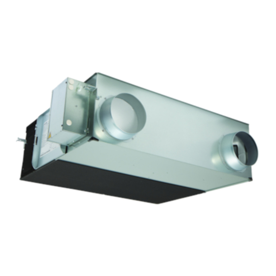
Page 2: Outline Drawings
Outline drawings Accessory parts LGH-F300, F470, F600RX Position where duct direction change is possible • Mounting screws ........x18 Damper plate Ceiling suspension fixture • Duct connecting flanges ......x4 Air exhaust fan (4 − 1/2" × 13/16" oval) (double flanges at SA and EA sides) •... -
Page 3: Standard Installation Examples
Standard installation examples • Duct length Return air grille Model Distance LGH-F300RX 40 inch or more LGH-F470RX 100 inch or more EA (exhaust air outlet) LGH-F600RX 100 inch or more Lossnay unit LGH-F1200RX 120 inch or more Supply air grille OA (outside air intake) •... - Page 4 Installation method (continued) CAUTION If the suspension bolts are short, change the • Before connecting the ducts, check that no debeis or any other mounting hardware. foreign matter (scraps of paper, vinyl, etc.) has found its way inside the ducts. For the model LGH-F300RX (1) Remove the hanger cover that is in the upper mounting position.
- Page 5 Installation method (continued) Electrical installation With this product, the wiring installation method will vary according to the design of the system. Perform electrical installation for each of the required sections. Names of components in control box LGH-F300, F470, F600RX LGH-F1200RX Earth pole LED4 LED1...
- Page 6 Installation method (continued) Wire connection diagram ----- Model LGH-F1200RX Connect the wires shown as dotted lines. Be sure to connect the grounding wire. Breaker should be provided by the customer. ORANGE TH1 (OA) TH2 (RA) ORANGE BROWN FUSE BROWN 250V6.3A BROWN YELLOW (CN16)
- Page 7 Installation method (continued) (1) Refer to the wiring diagram and screw down the grounding wire Connecting the power supply cable and transmission cables to the terminal block. (2) Secure the power supply cable and transmission cables using 1. Remove the screws and open the control the cord clamp and cable strap.
- Page 8 6. When connecting to City Multi, Lossnay remote controller (PZ-52SF- • Always separate the power supply cable and the Slim-Lossnay E) or Mitsubishi Electric Air-Conditioner Network System (MELANS). connection cable for the Lossnay by 5 cm or more to prevent malfunctioning of the unit.
- Page 9 Address setting is required. (Refer to function setting section.) 5. When switching high/low speed externally M-NET transmission cable: Connect any of the following -- City Multi indoor unit or Mitsubishi Electric (when CO sensor or other device is Air-Conditioner Network System connected) (MELANS) - to the Lossnay.
-
Page 10: Function Settings
Installation method (continued) When interlocking with the City Multi City City Lossnay Multi Multi M-NET transmission cable Remote controller for City Multi Keep the overall length of the transmission cable within 19685 inch. Note that the wiring length between the Lossnay and power supply unit (sold separately) or outdoor unit should be 7874 inch or less. -
Page 11: Trial Operation
Function settings (continued) 4. Settings for delay (of operation at start-up of 8. Settings for filter cleaning heating or cooling) Set the time for filter cleaning based on the estimated concentration of dust in the air. The factory setting is unlimited. (If the PZ-41SLB- This is the mode for delaying the operation of the Lossnay for 30 E is used, set it at the remote control.) minutes when the City Multi or Mr. - Page 12 I When an inspection number blinks on the remote controller, follow the procedures shown in the installation and operating manuals provided with the switch. I If the remote controller is not used, operate approximately 45 seconds after turning on the power for the Lossnay. MITSUBISHI ELECTRIC CORPORATION...
Need help?
Do you have a question about the Lossnay LGH-F300RX3-E and is the answer not in the manual?
Questions and answers