Advertisement
Quick Links
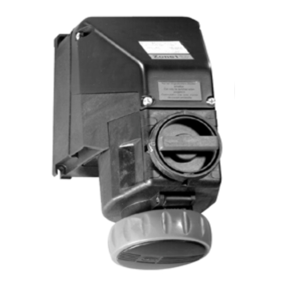
INSTALLATION, OPERATION & MAINTENANCE DATA SHEET
30 Amp Receptacle VSI30R and Plug VSI30P
For Hazardous and Corrosive Applications
Please read this entire document
before beginning any work.
1. Safety Instructions
Installation and maintenance of these plugs and receptacles
should only be performed by skilled and experienced
personnel in accordance with the National Electrical Code
(NEC) (NFPA 70) and any local regulations which relate to
hazardous (classified) locations.
CAUTION:
∗ Disconnect power supply before installing or servicing
these plugs and/or receptacles.
∗ A modification to this product, other than noted on this form,
is not permitted.
∗ Operate only undamaged and clean plugs & receptacles with
observations of the operating parameters in section 2.
∗ For a Class I Zone 1 conduit installation, conduit seals are
required; refer to NEC 505.16 (B) (1). For any other cable or
conduit installation NO seals are required.
∗ Use only approved wiring methods for the location, with the
associated conduit/cable fittings.
∗
The receptacle is suitable for use on a circuit capable of
delivering not more than 10,000 rms symmetrical amperes,
600V maximum, when protected by properly sized Class J
fuses.
2. Technical Data
Please refer to the technical data on the nameplates.
FM Project: 3024590 & CSA File 240743
2.1
Certification:
Class I, Zone 1 & 2, AEx de IIC T*
Class I, Division 2, Groups ABCD;
Class II, Division 1&2, Groups EFG; Class III
* Temp. Class T6 at Ta<40°C, T5 at Ta<55°C.
2.2 Ambient temperature range:
-22°F to +131°F (-30°C to +55°C).
2.3 Storage temperature range:
-67°F to +212°F (-55°C to +100°C).
2.4 Environmental protection:
Covers must be tight when plug is not inserted to maintain
environmental protection. Observe the labels on the plug and
receptacle.
3. Receptacle Installation
3.1 Enclosure mounting
Securely mount the receptacle in a vertical position using four
1/4" (6 mm) screws and suitable washers. Dimensions are
marked on the back of the receptacle housing.
P/N KIL00912478 FORM NO. K1287 1007 ERO-7-005-06
VSI30 Series Receptacles and Plugs
Ex de IIC T*
IP 66 / Type 3, 4, 4X.
HUBBELL ELECTRICAL PRODUCTS
A Division of HUBBELL INCORPORATED (Delaware)
3940 Martin Luther King Drive
St. Louis, Missouri 63113 USA
www.Hubbell-Killark.com
FOR
3.2 Conduit/Cable Installation
For conduit installation, connect rigid conduit to the hub and
avoid misalignment.
For cable installation, connect a listed cable fitting.
Conduit or cable fittings should not be tightened more than 50
ft-lbs (68 N-m) of torque.
3.3 Wiring
Open the terminal cover and connect the supply conductors. If
45°C, use 75°C rated wire; if T
T
is <
a
90°C wire
. The terminals accept up to two wires which are 14
AWG through 8 AWG per terminal. Allow proper length for
bending and cut the conductors to length. Strip the conductor
insulation 13/32" (10 mm) from the end. Insert the conductors
into the appropriate terminals which are marked to correspond
with the markings inside the plug. Torque all terminal screws to
16 in-lbs (1.8 N-m); including all unused terminals.
3.4 Installation of Auxiliary Contact Block (optional)
One or two blocks, either for I.S. or
non-I.S. circuits can be installed by
snapping them into either side of the
main terminal block. These contact
blocks also can be retrofitted and
must be installed according to IOM
Form No. K1289. See Parts and Accessories for block types.
3.5 Installation of Additional Entries
Additional top and side wiring entries can be installed in the
receptacle by punching through hole(s) 1-3/8" nominal dia. for
1" NPT. Use the mounting kit P/N YOST8571801290. The kit
contains one brass bonding plate, two locknuts with two 1"
NPT threaded holes and one bonding jumper with connection
screw. Insert entry fitting through the enclosure hole, tighten
into the bonding plate and secure with locknut. Connect the
bonding jumper to the terminal marked
bottom fitting can be installed by removing the close-up plug
and installing a 1" NPT fitting with locknut in it's' place. See
Parts and Accessories.
4. Horsepower Rating
Voltage AC
600V
480V
240V
120V
is > 45°C use
a
. A second 1" NPT
3-Phase
25 HP
SEE PLUG WIRING
20 HP
INSTRUCTIONS ON
10 HP
REVERSE SIDE
5 HP
Side 1 of 2
Advertisement

Subscribe to Our Youtube Channel
Related Manuals for Hubbell KILLARK VSI30 Series


Summary of Contents for Hubbell KILLARK VSI30 Series
- Page 1 HUBBELL ELECTRICAL PRODUCTS A Division of HUBBELL INCORPORATED (Delaware) 3940 Martin Luther King Drive St. Louis, Missouri 63113 USA www.Hubbell-Killark.com INSTALLATION, OPERATION & MAINTENANCE DATA SHEET VSI30 Series Receptacles and Plugs 30 Amp Receptacle VSI30R and Plug VSI30P For Hazardous and Corrosive Applications Please read this entire document before beginning any work.
- Page 2 INSTALLATION, OPERATION & MAINTENANCE DATA SHEET Figure 1 5. Wiring of Plug VSI30P 5.6 Connection to Terminals 5.1 Cord Type Flip the strain relief ( out of the way. Attach the leads to the appropriate terminals and torque with 16 in-lbs (1.8 N-m). Select a flexible cord with copper conductors of the CAUTION: The Equipment Grounding Conductor (green wire) appropriate insulation, ampacity, and temperature (75°C or...
Need help?
Do you have a question about the KILLARK VSI30 Series and is the answer not in the manual?
Questions and answers