
Related Manuals for Nixie Clock IV-11


Summary of Contents for Nixie Clock IV-11
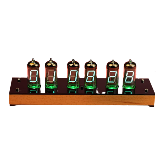
- Page 1 IV-11 VFD tube clock Assembly instructions v1.2.3 Designer: Yan Zeyuan. China Website: http://www.nixieclock.org E-mail: yanzeyuan@qq.com © 2019-07-12 NCH...
- Page 2 Attention ◇ Attention: All components are through-hole or DIP parts, please solder carefully; ◇ Warning: Make sure all components are pressed completely down on the PCB or the assembled clock will not fit in the housing. ◇ Warning: Before soldering, check the polarity each component. ◇...
-
Page 3: Table Of Contents
Identify electronic parts and installation method…………………..……………………………… 5 Assembly electronic components Assembly of low voltage and high voltage power modules..………………………………..…. 6 Assembly of the rest of components (except IV-11 tubes)……………………………………… 8 Assembly of IV-11 tubes………………………………………………………………………………………… 9 Assembly housing Step 1 Prepare bottom plate for assembly..…………………………….……………………………… 10 Step 2 Assemble spacers from bottom…………………………………….………………………………... -
Page 4: Parts List
Parts list Before getting started, please check the contents of the package. If any are missing, please contact the seller. Name Description Designator Footprint Value STC15F2K56S2 Programmed SKDIP28 TD62783APG U1, U2, U3, U4, U5, U6 DIP18 74HC595N U7, U8, U9, U10, U11, U12 DIP16 LPD8806D DIP16... -
Page 5: Pre-Installation Preparation Identify Electronic Parts And Installation Method
Pre-installation preparation Identify electronic parts and installation method. Resistor. Polarity-free Ceramic capacitor. Polarity-free Transistor. Notice the polarity Polarized capacitor. Notice the polarity Diode(Vertical). Notice the polarity Diode(Horizontal). Notice the polarity MOSFET. Notice the polarity IC. Notice the direction of installation Buzzer. -
Page 6: Assembly Electronic Components Assembly Of Low Voltage And High Voltage Power Modules
Assembly electronic components Assembly of low voltage and high voltage power modules The folloing components are needed: Notice Name Description Designator Footprint Value Polarized MC34063 U16, U17 DIP8 Polarized IRFU5305 TO-251 P-Channel Power MOSFET Polarized IRLU024 TO-251 N-Channel Power MOSFET Capacitor C8, C10 C-102... - Page 7 Assembly electronic components Please check the board to make certain that the parts are all soldered correctly, then for testing, place a wire jumper between TP5 and TP6 as shown below: Connect the power adapter. The voltage measured between TP2 and TP4 should be about 26.25 VDC;...
-
Page 8: Assembly Of The Rest Of Components (Except Iv-11 Tubes)
Assembly of the rest of the components (except IV-11tubes) Solder the rest of the components to the board, except IV-11 tubes. The polarity of the components must match the print on the board. The result should now look like this: Ambient light sensor and IR receiver need special attention during installation: ⚫... -
Page 9: Assembly Of Iv-11 Tubes
Please check the board and make sure the parts are soldered correctly. Then connect the power adapter and watch that six LEDs light up. The buzzer will make a“Beep”sound when the Power button of IR remote controller is pressed. Assembly of IV-11 tubes The following components are needed: Name Description... -
Page 10: Assembly Housing
Please check the board and make sure all tubes are soldered correctly, then connect the power adapter and check all functions following the user manual. Assembly housing The following parts are needed: Name Description Top and bottom plate Laser cut Wooden frame Copper spacer M3x18mm female-female for support top and bottom plate... -
Page 11: Step 3 Affix The Main Board
Assembly housing Step 3 Affix the main board Affix the main board to the base plate with 5pcs philips screws from the top. (M3 x 4mm) 11 / 14... -
Page 12: Step 4 Assembly Of The Wooden Frame
Assembly housing Step 4 Assembly of the wooden frame Assemble the wooden frame following the pictures below: Put down Move forward Two sockets will fit into the two holes of wooden frame. 12 / 14... -
Page 13: Step 5 Assembly Of The Top Plate
Assembly housing Step 5 Assembly of the top plate Fix 4pcs copper spacer with 4pcs hexagon socket head screws from the (M3x8mm) (M3x18mm) bottom. Then fix the top plate with 4pcs hexagon socket head screws from the top. (M3x8mm) Do not tighten 4pcs of screws too tight to prevent from cracking the top plate. ◼... - Page 14 Assembly housing Now it is time to enjoy your beautiful new IV-11 VFD tube clock, have fun! Any problems during assembly, please contact us. Designer: Yan Zeyuan. China Website: www.nixieclock.org E-mail yanzeyuan@qq.com 14 / 14...
Need help?
Do you have a question about the IV-11 and is the answer not in the manual?
Questions and answers