
Related Manuals for Nixie Clock DA-2000


Summary of Contents for Nixie Clock DA-2000
- Page 1 Numitron Clock Firmware V5 Operating Instructions Firmware V1 Supported Models: DA-2000 Clock IV-9 Clock DA2000-Clock-User-Manual-V5...
-
Page 2: About This Document
About this document This is the user instruction manual for the Nixie Clocks shown on the first page DA2000 Numitron Clock V1 • IV-9 Numitron Clock V1 • If you want to have the construction manual to guide you through the process of building the clock, please find the appropriate manual at: https://www.nixieclock.biz/Manuals.html There should have been an exact link to the clock manuals on the packing skip you received in... -
Page 3: Table Of Contents
Table of Contents About this document....................... 2 Contact Information........................ 2 Description..........................4 General........................... 5 First Start Mode........................5 Exit First Start mode......................5 Time Keeping (“Clock”) Mode....................5 Factory Reset........................5 Power on diagnostics......................6 Using the clock button......................7 Temporary Display Mode...................... -
Page 4: Description
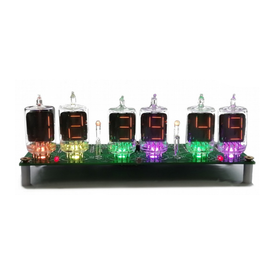
Description The Wemos Nixie Clock is a beautiful mix of old and new, resulting in a high accuracy, low power clock which will be a talking point in your home. The clock has the following features: Latest technology, highly reliable and accurate. -
Page 5: General
General The clock has different modes of operation, which you select using the push button. First Start Mode When you start the clock up the very first time, it will start in “First Start Mode”. This mode is intended to simplify the set up of the hardware. It cycles through the digits 00:00:00 - 99:99:99 and cycles though colours on the NeoPixels. -
Page 6: Power On Diagnostics
Power on diagnostics Every time you power the clock up, it will go through a self check routine to check the most important parts of the circuitry. Behind each digit there is a LED, which tells you the status on start up. -
Page 7: Using The Clock Button
Using the clock button Normally the clock is in “Time Display Mode”, which will show the time. If you press the button for differing lengths, different things will happen. “Short Press” (less than 1 second): A temporary display will be shown for 5 seconds. This is useful if you want to know the date, for example. -
Page 8: Temporary Display Mode
Temporary Display Mode Normally, the clock will show the time. To show additional information press the button with a “short” press. Each press cycles through the following information. After 5 seconds, the display will revert to the normal time display. Note that some of the options are not shown under all circumstances. -
Page 9: Status Leds
Status LEDs There are two status LEDs, one on the left of the “10X Hours” digit, and one on the right of the “1X Seconds” digit. You can configure these to tell you about the current clock status. By default, (or after a factory reset) the status LEDs will have the following meanings: Status LED Default Meaning Left Status LED... -
Page 10: Setting Mode
Setting Mode Usually you will want to set the clock up using the browser interface, because it is much easier to understand and quicker that way. To enter setting mode, press the button for more than 1 second (“Medium press”). Each Medium press of more than 1 second will move the setting mode onto the next. - Page 11 Mode Description Values Basic Settings 12 or 24 hour time. The hours are displayed in 12 or 24 “1” = 12 hour “--:--:07” hour mode. “0” = 24 hour seconds flashing default: 0 Blank leading “0”. Blank out the leading “0” from single “1”...
- Page 12 Mode Description Values Special Effects Settings Use LDR. If you disable the LDR, the tubes will always work “1” = enable “--:--:13” at maximum brightness. “0” = disable seconds flashing default: 1 Blank Mode. You can set the tubes, the LEDs or both the “0”...
- Page 13 Mode Description Values Green Channel Intensity. Sets the maximum intensity of Default: 15 “--:--:21” the green channel back light. This will be dimmed according Max: 15 seconds flashing to the display dimming. Min: 0 If you are in cycle mode, this setting will be skipped. Blue Channel Intensity.
-
Page 14: Setting Up The Wifi
Setting Up the WiFi This step sets up the clocks access to your WiFi and lets it start up and show a display. To complete this step you should have the display board finished and installed on the clock. Start the clock and wait for the LED behind the “1 X Minutes” digit to turn blue. This means that the clock has gone into “Access Mode”. - Page 15 should see that the landing page appears as shown above. When you see the landing page, press the “Configure WiFi” button, and you should see a list of available WiFi networks (it might take a few seconds to come up if you have many networks in your area).
-
Page 16: How To Access The Module After Wifi Set Up
If you have the module connected to the clock, you should get a time update after a maximum of two minutes. The module will disconnect you from it. Note: The time you get will be the time in Central Europe by default! Don’t worry, you can change this right away! See the section about “setting the time”... -
Page 17: Reading The Ip From The Clock Display
If you know the ESP ID you can access the clock directly using the address in your browser: http://esp_xxxxxx.local The “xxxxxx” is the ESP_ID and is made up of the last 6 places of the MAC address. Reading the IP from the clock display The clock will receive an IP address from your router, and you need to know the address in order to log into the module. -
Page 18: Setting The Time
Setting the time In order to make the time as flexible as possible, you have to enter a cryptic looking string into the “Time Zone String” setting on the time configuration page. For central Europe, (the default setting) this string is: “CET-1CEST,M3.5.0,M10.5.0/3"... -
Page 19: Some Common Time Zone Strings
Some common time zone strings Here is a short list of some common time zone strings. It is not a full list! (A full list can be found at: https://github.com/nayarsystems/posix_tz_db/blob/master/zones.csv Area Value United Kingdon GMT0BST,M3.5.0/1,M10.5.0 Central Europe CET-1CEST,M3.5.0,M10.5.0/3 US Mountain MST7MDT,M3.2.0,M11.1.0 US Central CST6CDT,M3.2.0,M11.1.0... -
Page 20: Web Interface
Web Interface Menu bar The menu bar allows you to select the page you are interested in: The options are: Page Description Summary Summary Information. This page provides information about the current status of the clock. It is not password protected. Time Server Time Server configuration. - Page 21 Option Description WIFI MAC This is the MAC address (unique hardware identifier) of the module in your network. You can use this if you have trouble finding the module in your router. WLAN SSID This is the WiFi name that you have connected to. NTP pool This is the NTP (Network Time Protocol) pool you are using to recover the current time from.
- Page 22 Option Description Motion If no motion sensor is installed, this value remains “Not installed”. If a motion sensor sensor is installed, this will show how log ago motion was last detected, and if the display is blanked. Time source Either “NTP”, “RTC” or “internal”. The value will show NTP is an update was received in the recent past and if we are still using the value of the NTP time update.
- Page 23 Option Description Free Heap The amount of volatile memory still available. Boot Version The boot loader version. The speed of the CPU. This is usually 160MHz. Frequency Flash The speed of the communication to the flash memory. This is usually 40MHz. Frequency SDK Version The version of the manufacturer’s software development kit.
-
Page 24: Time Server Options Page
Time server options page This page allows you to set how the time is retrieved from the internet and interpreted. This page may be protected by a password if this is configured. Please see the section on “Password Protection” for more information. Option Description NTP Pool... - Page 25 Option Description Update This will allow you to upload new firmware for the clock. You can select the Firmware firmware file to upload and it will be loaded and installed. Please make sure you are using a firmware which is suitable for the clock, otherwise it will stop working.
-
Page 26: Password Protection
Password Protection Configuration settings By default, the configuration options are password protected. You can change the username and password, or turn off the protection if you want to. By default the configuration protection settings are: Username admin Password setup OTA Update settings The “Over The Air”... -
Page 27: Display Blanking Mode
Display Blanking Mode If you have a motion detector installed If you have a motion detector installed (either a PIR or a microwave detector), the standard display blanking will be turned off and only the detector will be used for blanking the display, using the “PIR Timeout”... -
Page 28: Time Handling
Time Handling Time provider priorities The clock has three time providers: NTP time provider • RTC time provider • Internal time provider • The clock will always try to use the time provider furthest up the list, because each time you drop down to a lower priority time provider, features are lost. - Page 29 Page 29...
-
Page 30: Adding A Motion Sensor
Adding a motion sensor One of the best ways for reducing power consumption and extending tube life is to use a motion sensor. This can either be a PIR (recommended: HC-SR505) or a microwave detector (recommeded: RCWL-0516, shown on the right). RCWL-0516 HC-SR505 PIR You can also use other types of sensor, but it is important that you choose one with a 3.3V... - Page 31 The motion detector needs to be a type that takes a 5V input supply and has a 3V3 compatible output. Although the controller can accept a detector which has a 5V output, it is not recommended to use this type. Page 31...
-
Page 32: Factory Reset
Factory Reset To reset the clock back to initial settings, hold down the button directly after powering on, as soon as you see the second yellow LED come on. The clock will restart and the settings will have been reset. Everything will be reset back to the factory default state, and the clock will go back to “First Start Mode”. -
Page 33: External Power Supply
External power supply The power supply must be a 5V supply with a current capacity of at least 1A. A quality USB type charger is ideal. If you use a low quality or under-rated supply, you will notice that the tube filaments will be unevenly lit, and will flicker. -
Page 34: Updating The Firmware
Updating the Firmware The clock can be updated using a standard browser. This means that you can always get the latest firmware on to clock without any special tools. This is called an “Over The Air“ (“OTA”) update. To perform an update, get the latest firmware from the Nixieclock.biz website. Download the Zip file and unzip it. - Page 35 Page 35...
- Page 36 Now you can select the file to upload: and then press the update button. After a few seconds, you should get the confirmation that the file has been uploaded and the clock is rebooting: That’s it! Page 36...
- Page 37 Revisions: V0001: 22Sep2019: Initial version V0002: 20Oct2019: Clarified description of first start mode V0003: 21Oct2019: Added OTA info and description of mDNS V0004: 11Nov2019: No change V0005: 22Nov2019: Added information about exit setup mode using LEDs, SPIFFS diagnostic LED Page 37...
Need help?
Do you have a question about the DA-2000 and is the answer not in the manual?
Questions and answers