
Related Manuals for Nixie Clock Wemos Series


Summary of Contents for Nixie Clock Wemos Series
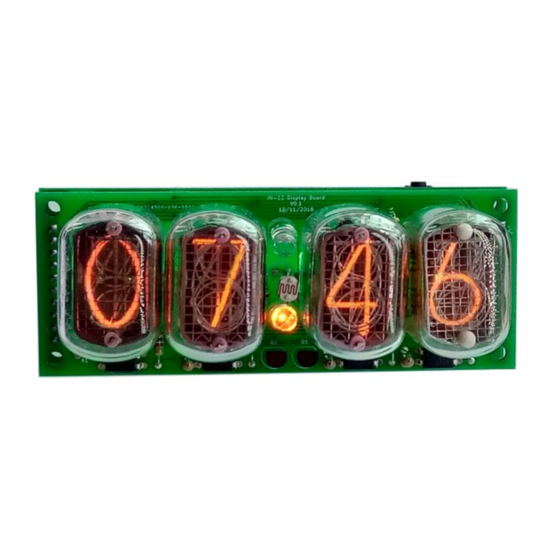
- Page 1 Wemos 4-Digit Nixie Clock Firmware V1 Operating Instructions Firmware V1 Supported Models: 4-Digit Wemos with IN-12 4-Digit Wemos with IN-2 4-Digit-User-Manual-V1...
-
Page 2: About This Document
About this document This is the user instruction manual for the Nixie Clocks shown on the first page 4-Digit Wemos Nixie Clock V1 • If you want to have the construction manual to guide you through the process of building the clock, please find the appropriate manual at: https://www.nixieclock.biz/Manuals.html... -
Page 3: Table Of Contents
Table of Contents About this document....................... 2 Contact Information........................ 2 Description..........................4 Safety............................5 General........................... 5 First Start..........................5 Exit First Start mode......................5 Time Keeping (“Clock”) Mode....................5 Factory Reset........................5 Power on diagnostics......................5 Using the clock button......................7 Temporary Display Mode...................... -
Page 4: Description
Description The Wemos Nixie Clock is a beautiful mix of old and new, resulting in a high accuracy, low power clock which will be a talking point in your home. The clock has the following features: Latest technology, highly reliable and accurate. -
Page 5: Safety
Safety The voltages produced in the High Voltage circuit can reach peaks of 400V! Take precautions not to electrocute yourself! If you are not sure what this means, please do not use this clock and return it for a full refund. A shock from the clock high voltage circuit is at least a nasty bite. - Page 6 Colour Meaning Seconds Yellow Checking the internal EEPROM for configuration information Green Recovered the configuration information correctly – previously stored settings have been loaded Failed to recover the configuration information – default settings will be used. Yellow Checking the access to the WiFi network Seconds Green Joined the previously stored WiFi access point...
-
Page 7: Using The Clock Button
Using the clock button Normally the clock is in “Time Display Mode”, which will show the time. If you press the button for differing lengths, different things will happen. “Short Press” (less than 1 second): A temporary display will be shown for 5 seconds. This is useful if you want to know the date, for example. -
Page 8: Temporary Display Mode
Temporary Display Mode Normally, the clock will show the time. To show additional information press the button with a “short” press. Each press cycles through the following information. After 5 seconds, the display will revert to the normal time display. Note that some of the options are not shown under all circumstances. -
Page 9: Setting Mode
Setting Mode Usually you will want to set the clock up using the browser interface, because it is much easier to understand and quicker that way. To enter setting mode, press the button for more than 1 second (“medium press”). Each medium press of more than 1 second will move the setting mode onto the next. - Page 10 Mode Description Values Basic Settings 12 or 24 hour time. The hours are displayed in 12 or 24 “1” = 12 hour 07 mm hour mode. “0” = 24 hour “07” flashing default: 0 “mm” = value Blank leading “0”. Blank out the leading “0” from single “1”...
- Page 11 Mode Description Values Special Effects Settings Use LDR. If you disable the LDR, the tubes will always work “1” = enable 15 mm at maximum brightness. If you enable it, the display “0” = disable “16” flashing brightness will vary with the ambient lighting. default: 1 “mm”...
- Page 12 Mode Description Values Back Light Mode. This sets the mode of the back light. “0” = Fixed 25 mm “1” = Pulse “25” flashing “Fixed” mode will show the back light color according to the “2” = Cycle “mm” = value Red, Green and Blue channel intensities.
- Page 13 Mode Description Values Clock version. Show the clock software version. “minutes” digits blanked then VV vv Digit Test. Will roll through all digits on all locations to check that the display is healthy.
-
Page 14: Setting Up The Wifi
Setting Up the WiFi This step sets up the clocks access to your WiFi and lets it start up and show a display. To complete this step you should have the display board finished and installed on the clock. Start the clock and wait for the LED behind the “10 X Seconds” digit to turn blue. This means that the clock has gone into “Access Mode”. - Page 15 When you see the landing page, press the “Configure WiFi” button, and you should see a list of available WiFi networks (it might take a few seconds to come up if you have many networks in your area). Select the network you want and enter the password for it. Note: The network you are using and the password for it will be remembered in your module, and it will try to reconnect to the same network.
-
Page 16: How To Access The Module After Wifi Set Up
Note: The time you get will be the time in Central Europe by default! Don’t worry, you can change this right away! See the section about “setting the time” for more information. How to access the module after WiFi set up Once the module is set up, you will need to log into it to configure the time server and set the configuration of the clock. -
Page 17: Common Address Ranges - Cable Networks
Common address ranges – Cable networks Note: If you are on a cable network, it is usual that you will get an address starting with “10” instead of “192.168” (such as “10.10.34.134”). Just follow the same steps nut substitute the address you received. -
Page 18: Some Common Time Zone Strings
Some common time zone strings Here is a short list of some common time zone strings. It is not a full list! (A full list can be found at: https://github.com/nayarsystems/posix_tz_db/blob/master/zones.csv) Area Value United Kingdon GMT0BST,M3.5.0/1,M10.5.0 Central Europe CET-1CEST,M3.5.0,M10.5.0/3 US Mountain MST7MDT,M3.2.0,M11.1.0 US Central CST6CDT,M3.2.0,M11.1.0... -
Page 19: Web Interface
Web Interface Menu bar The menu bar allows you to select the page you are interested in: The options are: Page Description Summary Summary Information. This page provides information about the current status of the clock. It is not password protected. Time Server Time Server configuration. - Page 20 Option Description NTP pool This is the NTP (Network Time Protocol) pool you are using to recover the current time from. This is the Posix Time Zone setting you are using. This string tells the clock what time offset from Greenwich Mean Time to use and how to deal with Daylight Savings Time.
- Page 21 Option Description Time source Either “NTP”, “RTC” or “internal”. The value will show NTP is an update was received in the recent past and if we are still using the value of the NTP time update. This will stay on “NTP” all the while we are in a valid reading, and for the same time afterwards.
- Page 22 Option Description SDK Version The version of the manufacturer’s software development kit. Chip ID Identifies the exact version of the main processor. Flash Chip ID Identifies the exact version/manufacturer of the flash memory. Flash size How big the flash memory is.
-
Page 23: Time Server Options Page
Time server options page This page allows you to set how the time is retrieved from the internet and interpreted. This page may be protected by a password if this is configured. Please see the section on “Password Protection” for more information. Option Description NTP Pool... - Page 24 Option Description Force This will cause the clock to access the NTP pool immediately and get the Update from current time, ignoring the “NTP Update Interval”. NTP now Perform This will cause the clock to forget all settings and go into the state it was in Factory when it was first programmed.
-
Page 25: Password Protection
Password Protection Configuration settings By default, the configuration options are password protected. You can change the username and password, or turn off the protection if you want to. By default the configuration protection settings are: Username admin Password setup OTA Update settings The “Over The Air”... -
Page 26: Display Blanking Mode
Display Blanking Mode If you have a motion detector installed If you have a motion detector installed (either a PIR or a microwave detector), the standard display blanking will be turned off and only the detector will be used for blanking the display, using the “PIR Timeout”... -
Page 27: Adding A Motion Sensor
Adding a motion sensor One of the best ways for reducing power consumption and extending tube life is to use a motion sensor. This can either be a PIR (recommended: HC-SR505) or a microwave detector (recommeded: RCWL-0516, shown on the right). RCWL-0516 HC-SR505 PIR You can also use other types of sensor, but it is important that you choose one with a 3.3V... -
Page 28: Tube Healing Mode
Tube Healing Mode After a long period of time, tube filaments which are not often used (e.g. the “9” on the tens of hours or minutes) can get dim, despite the ACP that is regularly done. If you make a “long” press of the button (more than 8 seconds), the clock will enter filament healing mode. -
Page 29: Factory Reset
Factory Reset To reset the clock back to initial settings, hold down the button directly after powering on, as soon as you see the first yellow LED come on. The clock will restart and the settings will have been reset. Everything will be reset back to the factory default state, and the clock will go back to “First Start Mode”. -
Page 30: External Power Supply
External power supply The perfect voltage for the external power supply is 7.5V or 9V DC. You can use 12V DC. If you use more than 12V be aware that you might have to provide a heat sink for the power components and adjust the HV voltage generation. - Page 31 Revisions: V0001: 22May2019: Initial version...
Need help?
Do you have a question about the Wemos Series and is the answer not in the manual?
Questions and answers