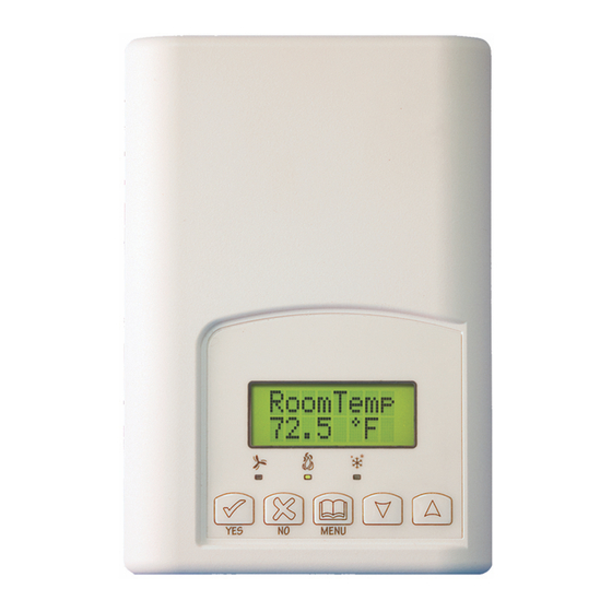
PIR Ready VT76x7 Series With & Without Local Schedule & With Humidification & Dehumidification Strategy Terminal Equipment Controllers Installation Guide F o r C o m m e r c i a l H V A C A p p l i c a t i o n s M a y 3 , 2 0 1 2 / 0 2 8 - 0 2 2 9 - R 4 ONTENTS...
NSTALLATION Remove the security screw on the bottom of Terminal Equipment Controller cover. Open unit by pulling on the bottom side of Terminal Equipment Controller (fig. 1). Remove wiring terminals from sticker. Please read the FCC ID and IC label installed in the cover upon removal of cover for the wireless products.
HEORY OF OPERATION The VT7600 uses a Viconics proprietary adaptive logic algorithm to control the space temperature. This algorithm controls the heating / air conditioning system to minimize overshoot while still providing comfort.
Features overview 7 day schedule models, 2 or 4 events Gas/oil or electric system compatibility for all type of applications Internal RH sensor and remote RH input with humidification and dehumidification sequence of operation embedded Remote outdoor sensing capability for added flexibility - System mode lock out - Humidity setpoint reset ...
Network ready All Viconics VT76x7 series Terminal Equipment Controllers are designed for stand-alone (Network Ready) operation. They can be fully integrated into your choice of automation systems using the available communication adapter options. If required, stand-alone (Network Ready) Terminal Equipment Controllers can be field retrofitted with the following communication adapters: VCM7607V5000B, Terminal Equipment Controller BACnet™...
Screw terminal arrangement 3 pole left top connector 5 pole left top connector Y2 Y1 G RC C RH W1 8 pole bottom connector HM AU DH DI HS OS HL Scom Wiring notes: Note 1: If the same power source is used for the heating stages, install jumper across RC & RH.
Remote humidity sensor accessories Model no. Description VH2020W1000 Wall mounted humidity sensor VH2020D10000 Duct mounted humidity sensor VH2020W1000, remote wall mounted room humidity sensor. This sensor can be used for: Remote return or room air humidity sensing with the sensor mounted on the wall. VH2020W1000 VH2020D1000, remote duct mounted humidity sensor c/w junction box.
User menu flow chart: NOTE: Prompts may not all be present depending on model selected If status is: Ov e r r i d e MENU Unoccupied s c h d Y / N If status is: Temporary Occupied Time, Re s u me Occupied hold or s c h d Y / N...
Page 11
Sequence of auto-scroll status display: ROOM CLOCK SYSTEM SCHEDULE OUTDOOR ALARMS TEMP & RH STATUS MODE STATUS TEMPERATURE x.x °C Monday Sys mode Outdoor or °F 12:00 Occupied Service auto x.x °C or°F XX % RH Sys mode Occupied Frost hold Sys mode Unoccup...
When cooling is ON, the COOL LED will illuminate Multistage and single Multistage Heatpump models stage models economizer models operation VT76xxH VT7600A, VT7652A, VT7605B & VT7656B VT7600B & VT7652B Fan LED When G Fan terminal When G Fan terminal When G Fan terminal operates...
Local keypad interface Each of the sections in the menu is accessed and configured using 5 keys on the Terminal Equipment Controller cover. The priority for the alarms is as follows: The YES key is used to confirm a selection, to move onto the next menu item and to manually scroll through the displayed information.
Occupied setpoints adjustments There is a default profile set in the Terminal Equipment Controller from the factory. This enables the Terminal Equipment Controller to operate as a non-scheduling unit in day mode operation at start up. Default temperature Default modes: setpoints: Occupied cooling setpoint = System mode = Auto...
Page 15
C) Temperature setpoints Permanent setpoint changes Temperat This menu permits the adjustment of all permanent temperature setpoints (occupied and unoccupied) as well as the desired temperature units (°F or °C). Permanent setpoints are written to RAM and EEPROM. Cooling Cooling Heating Heating setpoint setpoint...
50% RH and the dehumidification setpoint is changed from 70% RH to 45% RH, the humidification setpoint will be modified to 45% RH by the Terminal Equipment Controller. Humidification process Humidification process will only be allowed when the Terminal Equipment Controller is in heating mode (System Mode = Heat or System Mode = Auto and effective mode at the Terminal Equipment Controller is heat).
Page 17
E) System mode setting Sys mode set Y/N This menu is accessed to set system mode operation Use ▲▼ to set value, Yes key to confirm Sys mode Automatic mode Automatic changeover mode between heating and cooling operation auto Sys mode Cooling mode Cooling operation mode only cooling...
Page 18
Monday timer Tuesday timer Wednesday timer Other days are Schedule set Schedule set Schedule set identical No next No next No next Monday Tuesday Wednesda Selects the day to be scheduled or Yes down Yes down Yes down set? Y/N set? Y/N set? Y/N...
Page 19
** To schedule a day as occupied for 24 hours, set that day Occupied time to 12:00 AM and Unoccupied time to 11:59 PM There will be a 1 minute unoccupied period every night at 11:59 PM with this schedule configuration. H) Schedule set (4 events) Schedule This section of the menu permits the user to set the whether 2 or 4 events is needed.
Page 20
* Scheduling events to the same time will cancel the last period and leave the Terminal Equipment Controller in unoccupied mode Ex. #2 Residential Event Period 1 - Period 1 - Period 2 - Period 2 - Event 1 Event 2 Event 3 Event 4 Setpoint...
Enabling a permanent occupied or permanent unoccupied schedule hold will cancel any active override. The use of temporary setpoints during permanent hold is permitted. The duration of the temporary setpoint is as set per the TOccTime parameter. Ex. 3 hours Use ▲▼...
Page 22
This parameter (Personal Area Network Identification) is used to link specific Terminal Equipment Controllers to a single specific Viconics wireless gateway ( VWG ) For every Terminal Equipment Controller reporting to a gateway ( maximum of 30 Terminal Equipment Controllers per gateway ), be sure you set the SAME PAN ID value both at the gateway and the Terminal Equipment Controller(s).
Page 23
Controllers per gateway), be sure you set the SAME channel value both at the gateway and the Terminal Equipment Controller(s). Viconics recommends using only the usage of channels 15 and 25 only The default value of 10 is NOT a valid channel. The valid...
Page 24
DI 1 None, No function will be associated with the input Digital input no.1 Rem NSB, remote NSB timer clock input. Will disable the configuration internal scheduling of the Terminal Equipment Controller. The scheduling will now be set as per the digital input. The time is Open contact input = still displayed as information, but the menu part related to function not energized...
Page 25
Lockout Keypad lockout levels 0 = No lock 1 = Low level Default value = 0 No lock 2 = High level USER KEY FUNCTIONS Pwr del On initial power up of the Terminal Equipment Controller (each time 24 VAC power supply is Power-up delay removed &...
Page 26
Pband Adjust the proportional band used by the Terminal Equipment Proportional Band Controller PI control loop. setting Default value 2 = 2.0 °F ( 0.6 °C ) Note that the default value of 2.0 °F ( 1.1 °C ) gives satisfactory operation in most normal installation cases.
Page 27
Heat cph Will set the maximum number of heating stage cycles per hour Heating stages cycles under normal control operation. It represents the maximum number per hour of cycles that the equipment will turn ON and OFF in one hour. Default value = 4 Note that a higher C.P.H will represent a higher accuracy of control C.P.H.
Page 28
TOccTime Temporary occupancy time with occupied mode setpoints when Default value = 3 override function is enabled hours When the Terminal Equipment Controller is in unoccupied mode, function is enabled with either the menu or DI1 or DI2 configured as remote override input.
Page 29
C stage Will revert the operation of 2 stage Terminal Equipment Number of cooling stages Controller to single stage operation only when the second 2 stages model only cooling step is not needed. Default value = 2 stages 1 or 2 stages For heat pump models, HP stage selects the number of compressor stages H lock...
Page 30
Aux cont This contact can be used to energize peripheral devices such Auxiliary contact as: lighting equipment, exhaust fans, economizers, etc. configuration This contact will operate in parallel with the internal occupied/unoccupied schedule of the Terminal Equipment Default value = N.O. Controller or the remote NSB contact if DI1 or DI2 is used.
Page 31
RH HT Maximum outdoor air temperature for RH setpoint reset. Reset RH higher outside Only valid if an outdoor air sensor is connected at the Terminal temperature setpoint Equipment Controller or a network value is transmitted to the Default value = 32°F Terminal Equipment Controller.
RE SP The RH setpoint will be reset from the user setpoint to this value Reset humidity when the RH LT outside air temperature value is reached. setpoint Only valid if an outdoor air sensor is connected at the Terminal Default value = Equipment Controller or a network value is transmitted to the 20% RH...
Page 33
Wrong mode selected Select heating mode Terminal Equipment Select Occupied Hold in Schedule hold or Controller in Override to force the Terminal Equipment Unoccupied mode Controller Occupied heating setpoint Wait, the anti-cycling period will end and Anti-cycle delay active the equipment will start Heating setpoint is Raise the Heating setpoint satisfied...
UMIDITY ONTROL Humidity reset Humidity setpoint reset by outside air temperature If an outdoor air sensor is connected Terminal RH Set = 45% Equipment Controller or a value is received from the network, it can be used to reset the RH HT = 32°F humidity setpoint during the cold season...
PECIFICATIONS Terminal Equipment Controller power requirements: 19-30 VAC 50 or 60 Hz; 2 VA Class 2 RC to RH jumper 2.0 Amps 48 VA maximum Operating conditions: 0 °C to 50 °C ( 32 °F to 122 °F ) 0% to 95% R.H. non-condensing Storage conditions: -30 °C to 50 °C ( -22 °F to 122 °F ) 0% to 95% R.H.
Need help?
Do you have a question about the VT7600A and is the answer not in the manual?
Questions and answers