Table of Contents
Advertisement
Quick Links
• Always take time to fully read the Instructions and/or Operations Guide, and/or Basic Guide to Winching Techniques, in order to understand your winch and its operations.
• Never lean over battery while making connections.
• Never route electrical cables:
o Across any sharp edges.
o Through or near moving parts.
o Near parts that become hot.
• Always insulate and protect all exposed wiring and electrical terminals.
• Always install terminal boots as directed in installation instructions.
• Always tighten all nuts and bolts securely, per the installation instructions.
• Always perform regular inspections and maintenance on the plow mechanism, fasteners, cable and related hardware.
• Always replace all worn or damaged parts before operating.
• Never operate this WARN product with damaged or missing parts.
•
Always refer to the Installation and Specification Guide, supplied in the winch kit, for all wiring schematics and specific details on how to wire this WARN product to your vehicle.
•
4mm Allen Wrench
•
13 mm Wrench
•
Phillips Head Screwdriver
Please use the recommended torque specifications when assembling this product unless otherwise specified in the instructions.
FASTENER SIZE
FASTENER TORQUE
lb-ft
(N.m)
1/4"
8
(11)
5/16"
17
(23)
3/8"
30
(40)
7/16"
48
(66)
1/2"
74
(100)
9/16"
106
(144)
5/8"
148
(200)
3/4"
269
(364)
©2019 Warn Industries, Inc. WARN® and the WARN logo are trademarks of Warn Industries Inc.
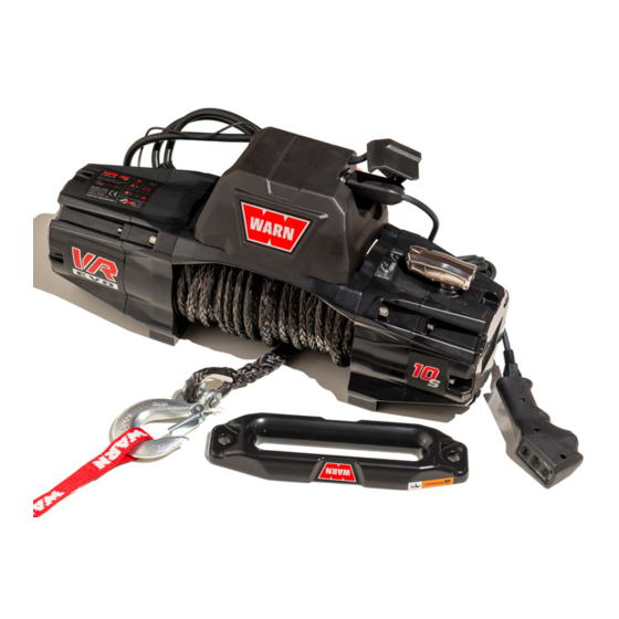
VR EVO CONTROL MODULE
Removal and Installation Instructions
G E N E R A L S A F E T Y P R E C A U T I O N S
IMPACT AND MOVING PARTS ENTANGLEMENT HAZARD
Failure to observe these instructions could lead to severe injury or death
Read installation and operating instructions thoroughly.
N O T I C E
EQUIPMENT DAMAGE
Read installation and operating instructions thoroughly.
T O O L S R E Q U I R E D
T O R Q U E S P E C I F I C A T I O N S
FASTENER SIZE
FASTENER TORQUE
M4
(2)
3
M5
(4.5)
6
M6
(7.5)
10
M8
(18)
25
M10
(37)
50
W A R N I N G
1
105938A0
Advertisement
Table of Contents

Related Manuals for Warn VR EVO


Summary of Contents for Warn VR EVO
- Page 1 EQUIPMENT DAMAGE • Always refer to the Installation and Specification Guide, supplied in the winch kit, for all wiring schematics and specific details on how to wire this WARN product to your vehicle. Read installation and operating instructions thoroughly. T O O L S R E Q U I R E D •...
- Page 2 REMOVING CONTROL PACK COVER FROM BASE PLATE Using a Phillips screwdriver, remove the four screws securing the base plate to the control pack cover. 105938A0 ©2019 Warn Industries, Inc. WARN® and the WARN logo are trademarks of Warn Industries Inc.
- Page 3 Remove the screw and the three black ground wires mounted next to the control module. You may now remove your control module completely and install new control module. 105938A0 ©2019 Warn Industries, Inc. WARN® and the WARN logo are trademarks of Warn Industries Inc.
- Page 4 (+) post on the contactor. Secure with nut, lockwasher and washer. Place control pack cover over base plate (covering internals). Control pack cover Contactor Control Module 105938A0 ©2019 Warn Industries, Inc. WARN® and the WARN logo are trademarks of Warn Industries Inc.
- Page 5 Always connect red (+) power cable ONLY to the positive (+) WARNING terminal of the battery. WARNING Always connect black ground (-) power cable ONLY to the negative (-) terminal of the battery. 105938A0 ©2019 Warn Industries, Inc. WARN® and the WARN logo are trademarks of Warn Industries Inc.
Need help?
Do you have a question about the VR EVO and is the answer not in the manual?
Questions and answers