Advertisement
Advertisement
Table of Contents

Related Manuals for Warn PULLZALL 24Vdc


Summary of Contents for Warn PULLZALL 24Vdc
- Page 1 SERVICE GUIDE WARN PULLZALL 24Vdc P/N 885005 & 885006 REPAIR / REPLACEMENT INSTRUCTIONS TROUBLE SHOOTING GUIDE 987606A1.doc Page 1 of 46...
- Page 2 This guide uses NOTICE to call attention to important mechanical information, and Note: to emphasize general information worthy of special attention. Notice This guide has been provided for use by WARN Authorized Service Centers. Any other use is prohibited. Caution...
-
Page 3: Table Of Contents
CONTENTS 1. GENERAL DESCRIPTION 2. DISASSEMBLY AND ASSEMBLY 2.1. Suggested Tools 2.2. Battery 2.3. Housing 2.4. Motor 2.5. Wire Rope Assembly 2.6. Safety Hook 2.7. Tail Hook 2.8. Gear Sets 2.9. Drum Assembly 2.10. Wiring Diagrams 2.11. Torque Specifications 3. PULLZALL TROUBLE SHOOTING 4. -
Page 4: General Description
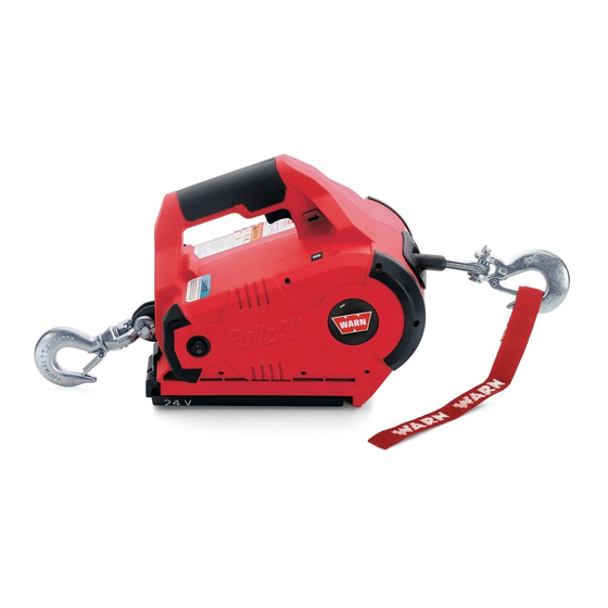
Cordless PullzAll 24VDC Specifications: 1. Part number 885005 (Domestic US), 885006 (International). 2. Light weight and portable. - Page 5 Convenient Forward / Electronic Load Reverse Switch Limiter with LED Variable Speed Trigger Switch Indicator for Operator Feedback 1,000lbs lifting/pulling Integrated Swiveling Anchor Hook On/Off Switch Powerful 24volt Recharge NiMH Battery Pack 15’ of Ø7/32” Wire Rope 987606A1.doc Page 5 of 46...
-
Page 6: Suggested Tools
2.1 SUGGESTED TOOLS 1. Hammer 2. Snap ring plier 3. Allen key set 4. Screw driver 5. Cutting plier 6. Pin remover (Punch) 7. Insulation tape 8. Gloves 987606A1.doc Page 6 of 46... -
Page 7: Battery
2.2 BATTERY 2.2.1 REMOVAL OF BATTERY Removing the Battery Pack • Verify the power switch is in the OFF position. • Push down the release button back of the Battery and slide the Battery away from the PullzAll body. • Remove the Battery when not in use. Permanent damage may occur if the unit is allowed to self-discharge in ON position 987606A1.doc Page 7 of 46... - Page 8 1. Hold the PullzAll in the position shown in figure, push down the release button at back of the Battery and slide the Battery away from the PullzAll body and pull Battery as shown direction 2. Slide away complete Battery from the PullzAll body 987606A1.doc Page 8 of 46...
- Page 9 2.2.2 ASSEMBLY OF BATTERY 1. Hold the PullzAll in the position as shown in figure. Slide the Battery pack into the body as shown direction 2. Slide Battery pack completely into the PullzAll body; make sure that the latch is fully engaged.
- Page 10 2.2.3 INSPECTION OF BATTERY • Inspect the Battery is not cracked or damaged. • Inspect whether the release button in hold position or not. Safety Rules & Guidelines: • Battery tools are always in an operative condition. Be aware of the possible hazards. Always remove the Battery when the PullzAll is not in use.
-
Page 11: Housing
2.3 HOUSING Before opening the Housing follow the below instructions: Power Switch: Always turn Power switch off. Permanent battery damage may occur if the unit is allowed to self discharge in the ON position. Removing the Battery Pack: • Verify the power Switch is in the OFF position. Push down the release Button back of the Battery and slide the Battery away from the PullzAll body as shown. - Page 12 2.3.1 REMOVAL OF HOUSING 1. Remove 6 screws (#6 x .75) from Handle 2. Remove 6 screws (#8 X 1.25) from the main body of the Housing. 3. Keep the assemblies on the work bench facing the cover in the direction shown in the figure.
- Page 13 4. Remove the Plastic Housing (left hand) from the assembly as shown in the figure. 5. Remove wiring connections of the Motor assembly from Trigger Switch (red and black wires) as shown in figure. 6. Remove the Main Chassis from the Plastic Housing.
- Page 14 2.3.2 ASSEMBLY OF HOUSING 1. Keep the right hand Housing on the work bench 2. Install the Chassis assembly into the right hand Housing as shown, verify the right hand frame Bracket is fully seated into the right Housing before installing the left hand Housing.
- Page 15 Keep the assembly on the work bench facing the cover in the direction shown in the figure. Install 6 screws (#8 X 1.25) from the main body of the Housing. Install 6 screws (#6 x .75) in Handle. Note: When replacing the Housings with a Housing Service kit, be sure to affix ALL appropriate labels from the service kit onto the new housings, using the housings being replaced as a guide for placement of your new labels.
-
Page 16: Motor
2.4 MOTOR 2.4.1 REMOVAL OF MOTOR Before removing the Motor follow the below instructions: 1. Remove the Motor Assembly from the End Housing by removing the 2 screws (M5 x .8 x 12), Qty 2 from the casting securing the Motor using a 4mm Allen Wrench. - Page 17 2.4.2 ASSEMBLY OF MOTOR 8. Install the Motor assembly in to the Chassis assembly. 9. Tighten the two CapScrews to secure Motor assembly in position. 10. Install Motor leads to top terminals of Switch per wiring diagram (Red to M+ or M1, Black to M- or M2).
-
Page 18: Wire Rope Assembly
2.4.3 INSPECTION OF MOTOR • Visual inspection. • Ensure that Motor has been properly placed inside the End Housing and the screw had been properly tightened 2.5 WIRE ROPE ASSEMBLY 2.5.1 REMOVAL OF WIRE ROPE Note: Prior to disassembly 1. Spool out all Wire Rope. 2. - Page 19 2. Using a punch or drift and hammer, tap the end of the Wire Rope to push the loop back through the Drum. 3. Use the pin remover (punch) to remove the Wire Rope from the Drum. 4. Remove the Stop Button from Drum by using snap ring plier as shown in the figure 987606A1.doc...
- Page 20 5. Straighten the bent Rope and pull the Rope out of Drum hole in the shown direction. 6. Remove the hawse fairlead from the Bracket of the Chassis. 7. Remove and discard the Tension Plate (if equipped). 987606A1.doc Page 20 of 46...
- Page 21 2.5.2 ASSEMBLY OF WIRE ROPE 1. Assemble the Hawse Fairlead to the Bracket of the Chassis. 2. Tighten the CapScrews with Allen key and opened end wrench. 3. Keep the insulation tape to the edge of the Wire Rope. 987606A1.doc Page 21 of 46...
- Page 22 4. Insert the Wire Rope into the Drum through the Hawse Fairlead. 5. Pull the wire from the other end of the Drum hole. 6. Bend the Wire Rope and insert in to the same hole in the direction shown in the figure.
- Page 23 8. Support one edge of the Wire and pull the other Wire as shown in the figure. 9. Verify Wire Rope stop button is inserted into the loop as shown before pulling the Wire Rope tight. 10. Hit wire rope loop with a hammer, so that the Wire Rope will be pushed in to the rope retention hole.
- Page 24 11. Check the Wire Rope so that it enters completely into the Drum hole. 12. Check from the other side of the Drum whether the Wire Rope is perfectly assembled to the Drum. 2.5.3 INSPECTION OF WIRE ROPE • Inspect the Wire Rope for signs of wear or damage. Worn and damaged parts must be replaced.
-
Page 25: Safety Hook
2.6 SAFETY HOOK 2.6.1 REMOVAL OF SAFETY HOOK To remove Safety Hook, follow the Instructions: 987606A1.doc Page 25 of 46... - Page 26 1. First straighten the bent end of the Cotter Pin by using pliers, and then pull away the Cotter Pin by holding head of the Pin with the help of pliers from the Pin. 2. Remove the Pin from the Safety Hook and Wire Rope.
- Page 27 3. Remove the Safety Hook from Wire Rope. 2.6.2 ASSEMBLY OF SAFETY HOOK To reassemble Safety Hook follow the Instructions: 1. Place the Safety Hook and align the mounting holes with the loop of the Wire Rope 2. Insert the Pin through Safety Hook and Wire Rope loop.
- Page 28 3. Insert the Cotter Pin inside the hole of the Pin and bend the ends of the Cotter Pin with the help of pliers. 2.6.3 INSPECTION OF SAFETY HOOK • Inspect the Hook for signs of wear and damage. • Hook damage examples: cracks, twisted components, excessive opening, seat wear, loose or damaged safety latch or corrosion.
-
Page 29: Tail Hook
2.7 TAIL HOOK Original Tailhook Assy Generation Tailhook Assy Service Part Tailhook Assy 987606A1.doc Page 29 of 46... - Page 30 2.7.1 REMOVAL OF TAIL HOOK To remove Tail Hook, follow the instructions below: 1. First straighten the bent end of the Cotter Pin, and then pull out. 2. Remove the Pin from the Hook assembly. 3. Remove the Tail Hook from Chassis assembly.
- Page 31 4. Remove Spacer Bracket from Chassis assembly while loosening the capscrew. 2.7.2 ASSEMBLY OF TAIL HOOK To reassemble Tail Hook follow the instructions 1. Place Spacer Bracket in Chassis assembly with capscrew and then apply the torque. 987606A1.doc Page 31 of 46...
- Page 32 2. Take the Tail Hook and align the mounting holes with the Spacer Bracket holes and Chassis assembly. 3. Insert the Pin through the Hook assembly. 4. Insert the Cotter Pin inside the hole of the Pin and bend the ends of the Cotter Pin with the help of pliers.
- Page 33 2.7.3 INSPECTION OF TAIL HOOK • Inspect the Hook for signs of wear and damage. • Hook damage examples: cracks, twisted components, excessive opening, seat wear, loose or damaged safety latch or corrosion. 987606A1.doc Page 33 of 46...
-
Page 34: Gearsets
2.8 GEARSETS • If the gearsets are worn or damaged, the entire PullzAll must be replaced, no replacement parts are available. 2.9 DRUM • If the drum is worn or damaged, the entire PullzAll must be replaced, no replacement parts are available. 987606A1.doc Page 34 of 46... -
Page 35: Wiring Diagrams
2.10 WIRING DIAGRAM WIRING DIAGRAM - 75824 987606A1.doc Page 35 of 46... - Page 36 2.10.1 WIRING DETAILS • Route Red Lead Wire from J3 Terminal on Circuit Board through Wire guides up into handle to Trigger Switch. • Route Red Lead Wire (soldered to Male Terminal Support) from J2 Terminal on Circuit Board through Wire guides up to where the male Terminal support is mounted.
- Page 37 Switch Pin-out Table Manufacturer name is embossed on switch. 2.10.2 REMOVAL OF WIRING 1. Remove the leads from Battery Terminals if required. Trigger Switch: 2. Remove the Wires from Trigger Switch. 987606A1.doc Page 37 of 46...
- Page 38 3. Remove the leads from Rocker Switch if required. 4. Take out Load limiter Board Assy from right Plastic Cover after unscrewing all the screws. 5. Remove the 3 leads from out Load limiter Board Assy if required. 987606A1.doc Page 38 of 46...
- Page 39 2.10.3 ASSEMBLY OF WIRING 1. Install Load limiter Board Assy to right Plastic Cover. 2. Install the two screws at Load limiter Board Assy with the help screw driver right Plastic Cover. 987606A1.doc Page 39 of 46...
- Page 40 Electronic Load Limiter 3. Push the Plastic Retainers out that secure the LED display 4. Install Battery Terminal into Right Hand Housing using Screws (6 x 0.50), Qty 2. 987606A1.doc Page 40 of 46...
- Page 41 5. Route Red Lead Wire (soldered to Male Terminal Support) from J2 Terminal on Circuit Board through wire guides up to rear of Housing to where the Male Terminal support is mounted. Trigger Switch 6. Route Red Lead Wire from load limiter circuit board J3 and black wire from load limiter J4 through wire guides up in to handle to Trigger Switch (Red to B+,...
- Page 42 7. Install leads to Rocker Switch 2.10.4 INSPECTION OF WIRING VISUAL INSPECTION • While disconnecting the connectors, never pull the Wiring Harnesses. Unlock the connector first and then pull them apart by holding Connectors themselves. • While connecting Connectors, also hold Connectors and put them together until they lock securely (a click is heard).
-
Page 43: Torque Specifications
2.11 TORQUE SPECIFICATIONS 987606A1.doc Page 43 of 46... -
Page 44: Pullzall Trouble Shooting
3. PULLZALL TROUBLE SHOOTING PROBLEM POSSIBLE CAUSE CORRECTIVE ACTION 1.1 PullzAll does not Battery is not fully charged. Charge Battery power in or pulls slowly. Loose connection on Battery Be sure all connections are tight or Motor Terminals. and clean. Do not let bottom nut or stud turn while tightening. - Page 45 1.3 Motor running but Damaged Geartrain Replace PullzAll not pulling 1.4 Motor does not run. Check Battery Condition Check Wiring condition visually (any short circuit ) Check Battery condition Repair or replace it with new Faulty Trigger Switch Repair or replace Switch Defective Motor Replace Motor 1.6 Electrical sparks...
-
Page 46: Service Part List
loose Terminals, etc... Damaged Wiring. Check Electrical Circuits 4. SERVICE PART LIST Description Part Number 1. Service Part -Motor Assembly 24vdc 77916 (Includes Motor & Screws) 2. Service Part - Variable Speed Trigger, 24vdc 77913 3. Service Part - Load Limiter Assembly, 24vdc 86355 (Includes LED Bezel, Screws and LED Retention Pins) 4.
Need help?
Do you have a question about the PULLZALL 24Vdc and is the answer not in the manual?
Questions and answers