Table of Contents
Advertisement
Quick Links
Advertisement
Table of Contents

Related Manuals for Essilor Instruments DELTA


Summary of Contents for Essilor Instruments DELTA
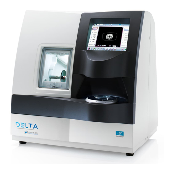
- Page 1 User Manual...
-
Page 2: Table Of Contents
> C ANUAL ONTENTS ONTENTS I. I NTRODUCTION II. F IRST TEPS WITH ELTA 1. Descriptive diagrams 2. Instructions for use a. Turn on the product b. Turn off the product c. Using the touch screen and keypads d. Work screens III. - Page 3 > C ANUAL ONTENTS 2. Modifying a shape a. Enlarging, reducing or rotating a shape b. Keep the perimeter constant c. Free-form modification d. Retouching a shape 3. Archiving/saving a shape VI. P REPARING A DRILLED JOB 1. Legend screen 2.
- Page 4 > C ANUAL ONTENTS c. Connections 2. Customize the tracer and the centering device a. Working modes and display precision b. Decentration mode c. Action bar d. Brightness e. Centering compensation 3. Adjusting the precision of the edger a. Adjusting the diameter of the finished lenses b.
- Page 5 > C ANUAL ONTENTS 2. General features 3. “Tracer centering device blocker” Function 4. “Edger” function XI. G ENERAL INFORMATION 1. Symbols 2. Modifications 3. Declaration of conformity 4. Copyright 5. Materials and products 6. Safety instructions: 7. Electromagnetic waves LOSSARY...
-
Page 6: Introduction
I. I NTRODUCTION... - Page 7 > I. I ANUAL NTRODUCTION The screens and features vary depending on the product configurations used. You have memory version: V2.0.0 Delta - Edging System > V1- 02-2020...
-
Page 8: First Teps With Elta
II. F IRST TEPS WITH ELTA... -
Page 9: Descriptive Diagrams
This chapter contains all the information relating to the product’s first use. • Product description p.10) • Using the device p.11) 1. D ESCRIPTIVE DIAGRAMS Trough Centering blocking environment Screen Main switch Connectors Manufacturer plate Power socket Solenoid valve socket Delta - Edging System > V1- 02-2020... -
Page 10: Instructions For Use
In this section, you will find all the information concerning the following: • The turning on andoff of the product p.12) p.12) • The use of the touch screen and the keyboards p.12) • The description of the main work screen p.15) Delta - Edging System > V1- 02-2020... -
Page 11: Turn On The Product
For a prolonged period of non-use (a few days), it is preferable to power down the product using the main switch. c. Using the touch screen and keypads Using the touch screen It is possible to navigate between the tracer-centerer-blocker screen and the edger screen in 2 different ways: Delta - Edging System > V1- 02-2020... - Page 12 When you need to enter or edit data, 2 types of keyboards automatically appear based on the information you want to enter: 1. The numeric keypad is displayed for entering values 2. The alphanumeric keyboard is displayed for storing, calling up and searching for jobs Delta - Edging System > V1- 02-2020...
- Page 13 • Go back • Confirm • Cancel and go back to the work screen Alphanumeric keyboard is displayed for storing, calling up and searching for jobs • & & Job reference (alphanumeric characters) Delta - Edging System > V1- 02-2020...
-
Page 14: Work Screens
Work area Tracer-centerer-blocker icon Call from the Tess tracer (optional) Actions available on the present screen For more information, consult the section performing an optical tracing > tracing environment > captioned screen. p.20) Delta - Edging System > V1- 02-2020... - Page 15 Posiblock display to be used depending on the job. Adjusting brightness and contrast Work area Tracer-centerer-blocker icon Actions available on the present screen For more information, see the section Center and block a lens> centering environment > Legend screen p.42) Delta - Edging System > V1- 02-2020...
- Page 16 Size increase / reduction Work area Edger icon Job call Actions available on the present screen Start the edging cycle For more information, consult the section Edging a lens > Edger environment > Menu screen p.94) Delta - Edging System > V1- 02-2020...
-
Page 17: Carry Out An Optical Tracing
III. C ARRY OUT AN OPTICAL TRACING... -
Page 18: The Tracing Environment
Description of the tracing screen p.20) • Jobs and working modes p.22) a. Legend screen Dimensions display ◦ A: A-dimension ◦ B: B-dimension ◦ D: D-dimension ◦ E: Larger radius from the Boxing center ◦ P: Perimeter Delta - Edging System > V1- 02-2020... - Page 19 Slight play between the demo lens and the frame ◦ Significant play between the demo lens and the frame To configure the size increase, consult the section configuring the tracer-centerer-blocker > Customizing the tracer > Work modes and display precision p.129) Delta - Edging System > V1- 02-2020...
-
Page 20: Jobs And Working Modes
1. Tracing or recovering a job from the database 2. Changing the shape and drilling position if necessary 3. Centering 4. Lens blocking 5. Edging preparation To activate this working mode, select the following parameters in the configuration screen: p.129) Delta - Edging System > V1- 02-2020... -
Page 21: Shape Management And Storage
This section explains how to manage the job list to store your shapes. • Description of the shape storage screen p.24) • Job list p.26) • Creating a job p.26) • Working in current job mode (job A) p.27) Delta - Edging System > V1- 02-2020... -
Page 22: Legend Screen
Sort the jobs ◦ ◦ Reference ◦ Date ◦ Types of jobs: ◦ Drilled ◦ Asymmetric tracings ◦ Creative shapes Selected job Select the eye to be displayed in the preview Shape preview Delta - Edging System > V1- 02-2020... - Page 23 Search for a job by ID or by reference Rename the selected job Duplicate the selected job Export the selected jobs To the Essibox or a PMS. Call the selected shape to the work area Delta - Edging System > V1- 02-2020...
-
Page 24: Job List
The tracing screen is displayed, the allocated ID and the job list symbol appear in the information bar. The tracer-centerer-blocker is ready for tracing. For further information, refer to the section concerning your job type. Delta - Edging System > V1- 02-2020... -
Page 25: Working In Current Job Mode (Job A)
For more information on entry and use of the keyboard, consult the section First steps > Using the tracer-centerer-blocker > Using the touchscreen and keyboards p.12) Press to select the ID field. & Press to delete the ID. Delta - Edging System > V1- 02-2020... -
Page 26: Optical Tracing
• Either three focimeter dots, • Or a horizontal line which must not touch the edges of the lens (a space of at least 5 mm is required). Avoid using red markers Delta - Edging System > V1- 02-2020... - Page 27 Press to select the type of play between the demo lens and the frame. Lower the tube. Position the reflector. Press on to start the tracing cycle. Delta - Edging System > V1- 02-2020...
- Page 28 > III. C ANUAL ARRY OUT AN OPTICAL TRACING > The following message is displayed: Press to confirm. > The following message is displayed: Position the lens. Press to confirm. Delta - Edging System > V1- 02-2020...
-
Page 29: Enter The Curve And Frame Base
Prerequisite: before entering the curve angle and the frame base, it’s necessary to perform the optical tracing of the pattern, a demo lens or a recut lens p.28) Delta - Edging System > V1- 02-2020... - Page 30 The vertical blue line must be in the center of the frame • The bridge of the frame superimposed on the base line. Use the buttons to align the light blue lines with the nasal and temporal ends of the rims. Delta - Edging System > V1- 02-2020...
-
Page 31: Case Of A Mechanical Tracing
Current job Turn on the Tess tracer. Perform a current tracing job on the Tess tracer. On the working screen of the machine, in tracer mode, press the icon of the Tess tracer Delta - Edging System > V1- 02-2020... - Page 32 Turn on the Tess tracer. Perform a numbered job reading on the Tess tracer. On the machine’s working screen, in tracer mode, press for a long time on the icon the Tess tracer Delta - Edging System > V1- 02-2020...
- Page 33 The following page appears: Complete the job number and press on > The following window is displayed: • press on to end the current job, • press on to cancel and obtain a new job number. Delta - Edging System > V1- 02-2020...
-
Page 34: Connection With A Phi Tracer
A beep rings out. > The form appears directly on the work screen of the product. The form arrives directly on the Delta 2 work screen, therefore it’s not possible to recall a previous shape.. Delta - Edging System > V1- 02-2020... -
Page 35: Center And Block A Lens
IV. C ENTER AND BLOCK A LENS... -
Page 36: Centering Environment
Description of the centering blocking system Pre-requisite: before carrying out the centering of the lens, supply a posiblock and a pad Essilor. Centering Lower the tube manually. Insert the posiblock and its pad in the centering device. Delta - Edging System > V1- 02-2020... - Page 37 As opposed to the other machines, the lens must be placed with convex side on the tube. Center the lens To center the lens, align the marking on the lens with the target according to the lens type used (bifocal, progressive, etc.). Delta - Edging System > V1- 02-2020...
- Page 38 Centering is manual. Block the lens Hold the lens with both hands and, put pressure down on the lens. Blocking is manual. > The tube drops and the posiblock is fixed on the lens. Delta - Edging System > V1- 02-2020...
- Page 39 Total PD By default, the value of the total half PD is marked "..." Clicking the buttons the default value changes to 65.0 mm. Visual cue of the frame positioned facing the screen Delta - Edging System > V1- 02-2020...
-
Page 40: Legend Screen
& ◦ Blocking in the optical center For further information, refer to the section Lens Centering > Blocking a lens > Preparing blocking p.62) Minimal diameter of the lens to be used Delta - Edging System > V1- 02-2020... - Page 41 Lens type selection ◦ Single vision lens & ◦ Progressive lens & ◦ Bifocal lens & ◦ Executive lens & ◦ Mid-distance lens & Value modification To reduce or increase the previously selected value. Delta - Edging System > V1- 02-2020...
- Page 42 The zoom is carried out directly by touching the screen on the desired area. There are three zoom modes: • Central • Temporal • Nasal To activate the display on the 1:1 scale by default, consult the section Tracer-centerer-blocker configuration > Customize > Work modes and display precision p.129) Delta - Edging System > V1- 02-2020...
-
Page 43: Calling Up A Shape
> You can then look for a job by ID, reference, date, job type (drilled, asymmetric tracings, creative shapes). For more information, see Make an optical tracing > Shape Management and Storage > Legend screen p.24) Delta - Edging System > V1- 02-2020... -
Page 44: Centering A Single Vision Lens
At the time of the release of the lens on the centering tube, be sure to align the three focimeter dots with the notches designed for this purpose in order not to alter the marking. Delta - Edging System > V1- 02-2020... - Page 45 Optical center of the lens (orange cross) and boxing center of the shape (blue cross) Centering marks Centering the lens Press to select the type of single vision lens. > The centering target is displayed: Delta - Edging System > V1- 02-2020...
- Page 46 > The lens is centered and ready to be blocked. HREE FOCIMETER DOTS ICRO ENGRAVINGS To block the lens, refer to the section Centering a lens > Blocking a lens p.62) Delta - Edging System > V1- 02-2020...
-
Page 47: Centering A Progressive Lens
Re-point the micro engravings on the felt; the points must have a diameter between 0. 5 and 1.5 mm We advise you to use the white felt tip marker supplied with the centerer-blocker to mark the lens. Delta - Edging System > V1- 02-2020... - Page 48 Lower the tube. Insert the posiblock and its pad in the centering device. Raise the tube back into centering position. Position the lens on the tube, with the convex side on the tube. Delta - Edging System > V1- 02-2020...
-
Page 49: Centering A Lens Using Manufacturer Markings
To block the lens, refer to the section Centering a lens > Blocking a lens p.62) b. Centering a lens using manufacturer markings Prerequisite: • The markings must be clear • The lens must at least have the following markings: Far vision mark Centering marks Delta - Edging System > V1- 02-2020... - Page 50 Position the lens on the tube, with the convex side on the tube. Slowly move the lens until manufacturer markings are: • Perfectly centered in the centering cross • Parallel to the horizontal lines Delta - Edging System > V1- 02-2020...
-
Page 51: Centering Bifocal/Trifocal Lenses
This section describes the centering procedure for a bifocal or trifocal lens with a straight, curved or round segment. Description of the centering target Centering cross (orange cross) and the boxing center of the shape (blue cross) Near vision mark Centering marks Delta - Edging System > V1- 02-2020... - Page 52 Position the lens on the tube, with the convex side on the tube. Move the lens slowly until the top of the segment is in the center of the target. SEGMENT OUND SEGMENT Delta - Edging System > V1- 02-2020...
-
Page 53: Centering An Executive Lens
For more information, consult the section performing an optical tracing > Optical tracing > Prepare the optical tracing of a demo lens or of recut lens. p.28) Delta - Edging System > V1- 02-2020... - Page 54 Enter the half PD (for near vision or far vision) and the frame height. > The target moves. Lower the tube. Insert the posiblock and its pad in the centering device. Raise the tube back into centering position. Delta - Edging System > V1- 02-2020...
-
Page 55: Centering A Mid-Distance Lens
Concerning the use of the stickers, be careful to change the centering tube with a larger diameter one to optimise the effectiveness of the sticker. This section describes the procedures for centering a mid-distance lens: • Using re-marked micro-engravings p.58) • Using manufacturer markings p.60) Delta - Edging System > V1- 02-2020... -
Page 56: Centering A Lens Using Re-Marked Micro-Engravings
Re-mark the micro-engravings with the marker; the diameter of points must be between 0.5 and 1.5 We advise you to use the white felt tip marker supplied with the tracer-centerer-blocker to mark the lens. Delta - Edging System > V1- 02-2020... - Page 57 Aligned on the line corresponding to the PRP (Prism Reference Point) of the lens The PRP value of Essilor mid-distance lenses is 6 mm. This may vary depending on the manufacturer of the lenses. Delta - Edging System > V1- 02-2020...
-
Page 58: Centering A Lens Using Manufacturer Markings
To block the lens, refer to the section Centering a lens > Blocking a lens p.62) b. Centering a lens using manufacturer markings Prerequisite • The markings must be clear • The lens must at least have the following markings: Centering cross Centering marks Delta - Edging System > V1- 02-2020... - Page 59 Position the lens on the tube, with the convex side on the tube. Slowly move the lens until manufacturer markings are: • Perfectly centered in the centering cross • Parallel to the horizontal lines Delta - Edging System > V1- 02-2020...
-
Page 60: Blocking A Lens
Blocking preparation p.62) • Blocking p.64) a. Prepare blocking Several accessories are available to perform blocking: • Posiblocks and pads • Tubes Posiblocks and pads 22 mm posiblock 18 × 14 mm posiblock Magnet Delta - Edging System > V1- 02-2020... - Page 61 The large tube has a diameter of 53 mm. This is an optional accessory and will only be used in specific cases, such as hydrophobic lens stickers. It is mounted instead of the small tube, by a simple system of bayonet assembly. Delta - Edging System > V1- 02-2020...
-
Page 62: Blocking
Use the posiblock adapted to the shape, indicated at the bottom right of the screen: Place the posiblock on the pad and press firmly, with the self-adhesive face upwards and tabs towards the left. Remove the film from the self-adhesive face. Lower the tube. Delta - Edging System > V1- 02-2020... - Page 63 Position the posiblock within the boundary of the tube designed for this purpose. Raise the tube back into centering position. After centering the lens, apply pressure with two hands on the tube in order to lower it. Delta - Edging System > V1- 02-2020...
- Page 64 For a hydrophobic lens, be careful to use the large diameter tube and the stickers designed for this purpose. Center and block the second lens. > The edging preparation screen is displayed automatically. Center and block the second lens. > The edging preparation screen is displayed automatically. Delta - Edging System > V1- 02-2020...
-
Page 65: Blocking Control And Compensation
If the lens slips during blocking, it is possible to compensate for this difference. To do this and only after blocking the lens: Click on > The following message is displayed: Press to confirm. Delta - Edging System > V1- 02-2020... - Page 66 > IV. C ANUAL ENTER AND BLOCK A LENS Lower the tube. Position the blocked lens in the center. Adjust the (orange) mire using arrows Delta - Edging System > V1- 02-2020...
- Page 67 The correction of the centering values can be modified by 0.5° in a range of [-3°; +3°] When a job is re-used, the compensation value is saved in order to maintain the history of the job. Delta - Edging System > V1- 02-2020...
- Page 68 V. M ODIFYING THE LENS SHAPE...
-
Page 69: Modifying The Lens Shape
(grey) Part of the shape not selected for the current modification ◦ (yellow) Limit of the drilling zone ◦ (red) Non-machinable shape ◦ (blue) Reference drilling points Binocular view Half PD and pupillary height Delta - Edging System > V1- 02-2020... -
Page 70: Modifying A Shape
• the free modification , within the constraints pertaining to lens edging p.78) • the retouching of a shape in the event of possible tracing defects p.79) Delta - Edging System > V1- 02-2020... -
Page 71: Enlarging, Reducing Or Rotating A Shape
> The shape is modified. > The original shape is displayed in light red. Example of an A-dimension reduction Example of a half B-dimension reduction Delta - Edging System > V1- 02-2020... - Page 72 The original shape is displayed in light red. With every press of the buttons the A-dimension changes. The B-dimension is then modified while retaining the A/B ratio. Example of a total enlargement of the shape: Delta - Edging System > V1- 02-2020...
-
Page 73: Keep The Perimeter Constant
This function allows you to change the shape of the lens by maintaining a constant perimeter. For example, if I decrease the A dimension of the lens, the B dimension will increase so that it maintains the same perimeter. Press first on to select the scaling change. Delta - Edging System > V1- 02-2020... - Page 74 : A-dimension • : B-dimension Value of increased dimension Shown in blue Dimensional value decreased Shown in green Once the shape is modified, press to save and go back to the centering screen. Delta - Edging System > V1- 02-2020...
-
Page 75: Free-Form Modification
Move the line starting at the boxing center to orient the modification. Use the buttons to reduce or enlarge the shape. > The shape is modified. > The original shape is displayed in light red. Delta - Edging System > V1- 02-2020... -
Page 76: Retouching A Shape
The types of retouch available vary according to the size of the selected area. • Retouch to create a straight line • Retouch to create a curve • Retouch to create an angle > The selected area is retouched. Delta - Edging System > V1- 02-2020... -
Page 77: Archiving/Saving A Shape
Enter a reference for the shape to be saved. Press to confirm. > The shape is archived in a new job with a new ID and is displayed in the shape modification screen. Delta - Edging System > V1- 02-2020... -
Page 78: Preparing A Drilled Job
VI. P REPARING A DRILLED JOB... -
Page 79: Legend Screen
The drilling function is not available for glass lenses. 1. L EGEND SCREEN The drilling screen is accessible: • from the centering screen, • from the edging preparation screen. Press to prepare a drilled job. Delta - Edging System > V1- 02-2020... - Page 80 A drilling point with a color infill indicates non through-drilling Curve angle Binocular view Active eye The selected eye has an orange frame around it. Type of drilling ◦ Drill-hole ◦ Slot ◦ Notch Delta - Edging System > V1- 02-2020...
- Page 81 Archive the shape and create a new job based on the job displayed Back to the centering screen ◦ Press to save the changes and return to the centering screen. ◦ Press to return to the centering screen without saving the changes. Delta - Edging System > V1- 02-2020...
-
Page 82: Configuring A Drilling Point
On the tracer-centerer-blocker, you can configure up to 6 drilling points per side (nasal and temporal) of a shape. Delta - Edging System > V1- 02-2020... -
Page 83: Delete One Drilling Point
The numeric keypad is displayed. You can also use the buttons to decrease or increase the selected value. Enter the new value of the parameter and press to confirm. > The drilling point has been modified. Delta - Edging System > V1- 02-2020... -
Page 84: Adjusting The Position Of A Drilling Point
• For a drill-hole, it is the center. • For a slot and a notch, the entrance point is always on the side which is furthest away from the edge of the lens: Delta - Edging System > V1- 02-2020... - Page 85 Y position of the drilling point. > The numeric keypad is displayed. Enter the new value and press to confirm. > The drilling coordinates have been modified. Delta - Edging System > V1- 02-2020...
- Page 86 • Each side (nasal and temporal) has its reference drilling point, identified by its dark blue colour • It is identified by the symbol # on the left of its coordinates. Delta - Edging System > V1- 02-2020...
-
Page 87: Drilling Models
The distance between the reference drilling point and the edge of the lens From the drilling positioning screen, press to access the list of drilled jobs saved in the shape management screen. Select the desired job as a drilling model. Delta - Edging System > V1- 02-2020... - Page 88 The settings of each drilling point in the model • The Y coordinates of each drilling point in relation to the boxing center of the model shape • The distance between the reference drilling point and the edge of the lens Delta - Edging System > V1- 02-2020...
-
Page 89: Saving A Model
The new job with the new ID is displayed on the drilling screen. Press to return to the centering screen. You can go back to the previous job via the shape management screen if it has an ID. Delta - Edging System > V1- 02-2020... -
Page 90: Edging A Lens
VII. E DGING A LENS... -
Page 91: Edger Working Environment
This section describes: • The edger work screen p.94) • Shape call-up procedure p.96) • Putting the lens in place p.97) a. Legend screen Size reduction / increase (mm) Job call button from the tracer Delta - Edging System > V1- 02-2020... - Page 92 2-star cycle For all types of materials. This cycle offers a more sophisticated edging mode than the standard cycle, dedicated to thin lenses or hydrophobic lenses. Polishing ◦ Polished lens ◦ Non-polished lens Delta - Edging System > V1- 02-2020...
-
Page 93: Calling Up A Shape
A reminder of the type of posiblock required is displayed on the shape. It is crucial to use the proper accessory to edge the lens. Otherwise, an error message is displayed at the start of the cycle. Delta - Edging System > V1- 02-2020... -
Page 94: Lens Set-Up And Feeling
To interrupt the feeling cycle at any time, press > The feeling of the lens is carried out first on the rear surface (concave face of the lens) and then on the front surface (convex face of the lens). Delta - Edging System > V1- 02-2020... -
Page 95: Perform A Beveling
The bevel finish is selected by default. • The automatic mode is selected by default. Select lens material. Select the type of cycle. Choose whether or not to polish and/or chamfer your lens. Delta - Edging System > V1- 02-2020... -
Page 96: Legend Screen For Customized Bevels
Otherwise, start edging the second lens. Select the lens directly on the screen, on the left or right of the work area. > The edging screen for the second lens is displayed. All finishes chosen and the modifications made are kept. b. Legend screen for customized bevels Automatic bevel Delta - Edging System > V1- 02-2020... - Page 97 Flat representation of the lens making it possible to assess the distances between the bevel crest and the front & rear surfaces of the lens. Trajectory modification ◦ General modification of the bevel curve ◦ Modification of the bevel curve at a particular point ◦ Displacement of the bevel curve Delta - Edging System > V1- 02-2020...
-
Page 98: Customized Beveling
Choose whether or not to polish and/or chamfer your lens. For more information, consult the section Edging a lens > Perform a polishing and Edging p.121) a lens > Perform a chamfering p.121) Delta - Edging System > V1- 02-2020... -
Page 99: Modifying The Bevel Curve
Press from the customized bevel finish screen. > You will access the trajectory modification screen. Press to select the general modification of the bevel curve. Delta - Edging System > V1- 02-2020... -
Page 100: Modifying The Bevel Curve At A Particular Point
Press from the customized bevel finish screen. > You will access the trajectory modification screen. Press to select modification of the bevel curve at a particular point. Delta - Edging System > V1- 02-2020... -
Page 101: Displacing The Bevel Curve
The displacement of the bevel curve makes it possible to move the bevel without modifying its curve. Press from the customized bevel finish screen. > You will access the trajectory modification screen. Press to select the displacement of the bevel curve. Use the buttons to displace the bevel curve: Delta - Edging System > V1- 02-2020... -
Page 102: Make A Bevel/Tilted Groove
1. A point on the lens, which will remain fixed and will not be parameterized (green square) 2. The opposite point (at 180°) that will be configurable (blue square) Call the shape and select the custom mode Press to validate the choice. Delta - Edging System > V1- 02-2020... - Page 103 Depending on the choice you have set, select (lens base) or (frame base). Press to select the displacement of the bevel or groove curve. Press > Two zoom windows are now visible. Fixed groove/bevel display Configurable groove/bevel display Delta - Edging System > V1- 02-2020...
-
Page 104: Grooving
A general modification of the groove curve p.112) ◦ A modification at a point of the groove curve p.113) ◦ A displacement of the groove curve p.114) • You can consult the description of the customized groove screen p.109) Delta - Edging System > V1- 02-2020... -
Page 105: Automatic Grooving
Choose whether or not to polish and/or chamfer your lens. For more information, consult the section Edging a lens > Perform a polishing and Edging p.121) a lens > Perform a chamfering p.121) Close the door. Delta - Edging System > V1- 02-2020... -
Page 106: Customized Groove Legend Screen
Otherwise, start edging the second lens. Select the lens directly on the screen, on the left or right of the work area. > The edging screen for the second lens is displayed. All finishes chosen and the modifications made are kept. b. Customized groove legend screen Automatic groove Delta - Edging System > V1- 02-2020... - Page 107 Flat representation of the lens making it possible to measure the distances between the groove and the front & rear surfaces of the lens. Modify the trajectory ◦ General modification of the groove curve ◦ Modification of a point in the groove curve ◦ Displacement of the groove curve Delta - Edging System > V1- 02-2020...
-
Page 108: Customised Grooving
Choose whether or not to polish and/or chamfer your lens. For more information, consult the section Edging a lens > Perform a polishing and Edging p.121) a lens > Perform a chamfering p.121) Delta - Edging System > V1- 02-2020... -
Page 109: Modifying The Groove Curve
Press from the customized groove finish screen. > You will access the trajectory modification screen. Press to select the general modification of the groove curve. Delta - Edging System > V1- 02-2020... -
Page 110: Modifying A Point In The Groove Curve
Press from the customized groove finish screen. > You will access the trajectory modification screen. Press to select modification of a point in the groove curve. Delta - Edging System > V1- 02-2020... -
Page 111: Displacement Of The Groove Curve
The displacement of the groove curve enables you to move the groove without modifying its curve or perimeter. Press from the customized groove finish screen. > You will access the trajectory modification screen. Press to select the displacement of the curve. Use the buttons to displace the curve. Delta - Edging System > V1- 02-2020... -
Page 112: Produce A Flat-Edge Finish
Call up the desired shape located on the tracer. > The shape is displayed on the edger work screen. Select lens material. Press to select the flat-edge finish. Select the type of cycle. Delta - Edging System > V1- 02-2020... -
Page 113: Perform A Drilled Job
◦ Customized drilling: you can modify the diameter and angle for each drilling point. • You can consult the description of the customized drilling screen p.118) Delta - Edging System > V1- 02-2020... -
Page 114: Automatic Drilling
Otherwise, start edging the second lens. Select the lens directly on the screen, on the left or right of the work area. > The edging screen for the second lens is displayed. All finishes chosen and the modifications made are kept. Delta - Edging System > V1- 02-2020... -
Page 115: Legend Screen For Customized Drilling
Select the drilling points ◦ Nasal side ◦ Temporal side ◦ All drilling points Modify the selected value Modify the diameter ◦ diameter (mm) ◦ difference between the initial value and the modified value Delta - Edging System > V1- 02-2020... -
Page 116: Customized Drilling
Choose whether or not to polish and/or chamfer your lens. For more information, consult the section Edging a lens > Perform a polishing and Edging p.121) a lens > Perform a chamfering p.121) Close the door. Delta - Edging System > V1- 02-2020... - Page 117 If necessary, select the drilling point(s) you want to modify. If necessary, modify the diameter and/or angle of the selected drilling point. > The difference between the initial value and the modified one is displayed in the delta column. Press >...
-
Page 118: Perform A Polishing
Standard value of a small chamfer: 0.20 mm • Standard value of a large chamfer: 0.40 mm Before you select a type of chamfer, make sure it is compatible with the lens characteristics: Delta - Edging System > V1- 02-2020... - Page 119 The chamfers available also depend on the lens shape and the posiblock used when blocking. Press on the buttons to configure a small chamfer, a large chamfer or no chamfer on the front and rear surfaces of the lens. Delta - Edging System > V1- 02-2020...
-
Page 120: Perform A Retouching
If your job is perfect, proceed with the edging of your second lens. > All of the selected finishing options and modifications made are kept. • If the lens requires adjustment, do a retouch on the edged lens to obtain optimal results. Delta - Edging System > V1- 02-2020... - Page 121 The edging screen for the second lens is displayed. > All finishes chosen and the modifications made are kept. The retouch done on the first lens is automatically saved for the edging of the second lens. Delta - Edging System > V1- 02-2020...
-
Page 122: Set Up The Product
VIII. S ET UP THE PRODUCT... -
Page 123: Configure The Tracer-Centerer-Blocker And The Edger
Date Use the arrows to set the date. Type of date display Select the type of display out of the available formats. Language Select the flag corresponding to your language. Delta - Edging System > V1- 02-2020... -
Page 124: Screensaver
The following screen is displayed: Screensaver display Activate or deactivate the screensaver. Triggering Set the waiting time before the display of the screensaver (in seconds). Transition Set the transition time between each image (in seconds). Delta - Edging System > V1- 02-2020... -
Page 125: Connections
Press on this button to activate or deactivate the Ethernet port. Addressing mode ◦ Static: mandatory if the machines are connected to one another ◦ DHCP: the addressing settings of the optician’s network have been recovered Delta - Edging System > V1- 02-2020... -
Page 126: Customize The Tracer And The Centering Device
• the measurement accuracy display, • the centering page zoom, • the blocking mode in the boxing center or optical center. To reach this menu since your working screen, select > > > Delta - Edging System > V1- 02-2020... - Page 127 ◦ Major slack (from 0 to 1 mm) Boxing cross ◦ Activated ◦ Deactivated Warning message on import of a current Tess job (if the Tess connection is activated) ◦ Activated ◦ Deactivated Delta - Edging System > V1- 02-2020...
-
Page 128: Decentration Mode
Decentration mode This menu enables you to select a default input mode for decentration data. To reach this menu from your working screen, select > > > Delta - Edging System > V1- 02-2020... -
Page 129: Action Bar
To reach the customization menu of the action bar from your working screen, select > > > Delta - Edging System > V1- 02-2020... - Page 130 Monocular right eye only Frame type ◦ Metal frame ◦ Plastic frame ◦ Optyl frame, for particularly flexible frames ◦ Grooved frame ◦ Drilled frame Tracing mode ◦ Demo lens / Recut lens ◦ Pattern Delta - Edging System > V1- 02-2020...
-
Page 131: Brightness
You can adjust the default brightness of the work area and/or the touch screen to improve your view of the lens to be centered. To reach the luminosity customization menu from your working screen, select > > > The following settings are displayed: Delta - Edging System > V1- 02-2020... -
Page 132: Centering Compensation
The following screen will appear: Change in right eye half PD Change in left eye half PD PD modification This value corresponds to the sum of the two 1/2 pupillary distances. Height modification Delta - Edging System > V1- 02-2020... -
Page 133: Adjusting The Precision Of The Edger
If lenses of a particular material always seem too small or too big after edging, you can adjust their diameter according to the type of frame. To access this menu from the work screen of your edger, select > > > > Delta - Edging System > V1- 02-2020... -
Page 134: Adjusting The Position Of The Bevel And Groove
After edging a lens, if the position of the bevel or groove always seems too close to the front or rear surface, you can adjust it. To access this menu from the work screen of your edger, select > > > Delta - Edging System > V1- 02-2020... -
Page 135: Adjusting The Diameter Of Drill-Holes
After drilling a lens, if the diameter of the holes always seems too small or too big, you can adjust it according to the diameter of the drill bit used and the lens material. To access this menu from the work screen of your edger, select > > > Delta - Edging System > V1- 02-2020... -
Page 136: Adjusting The Chamfer
After edging a lens, if a chamfer always seems too small or too big, you can adjust its size according to the lens material. To access this menu from the work screen of your edger, select > > > Delta - Edging System > V1- 02-2020... -
Page 137: Adjusting The Groove
After edging a lens, if the width or depth of the groove always seem too close too small or too big, you can adjust them. To access this menu from the work screen of your edger, select > > > Delta - Edging System > V1- 02-2020... -
Page 138: Set Default Size Settings
To access this menu from your edger work screen, select > > The default setting only applies to the following settings: • frame material • 1 or 2-star cycle • polishing • front and rear surface chamfering Delta - Edging System > V1- 02-2020... - Page 139 If, out of the last 30 lenses, 20 have been plastic edged, then the material proposed for the 31st lens will be plastic. Forced Choice You set your choice by default. To make this choice. Go to the edging screen. Delta - Edging System > V1- 02-2020...
- Page 140 Set the default choice you want. Return to the default edging settings menu > Select "forced choice" and press the menu bar to update it. > The "?" icon disappears. To change the default choice: restart the procedure. Delta - Edging System > V1- 02-2020...
-
Page 141: Restoring The Factory Settings
At the bottom right of certain tracer configuration screens, the button can be used to restore the factory settings of the page. • Press to cancel and go back to the settings screen. • Press to confirm reinitialization. Delta - Edging System > V1- 02-2020... -
Page 142: Maintenance And Servicing
IX. M AINTENANCE AND SERVICING... -
Page 143: Perform The Autotest Of The Tracer
Camera test LED band tests Principal LED test There exist two types of diagnosis: • Diagnoses carried out with reflectors: test camera and main LED • Diagnoses carried out without reflectors: LED band test Delta - Edging System > V1- 02-2020... -
Page 144: Performing The Edger Autotest
To test the proper performance of the edger, select > > > on your working screen. Edger autotests Locking of the door Initialisation and rotation of lens shafts Reproducer: lens shaft raising and lowering Closing of lens shafts Wheel rotation Delta - Edging System > V1- 02-2020... -
Page 145: Checking And Calibrating The Tracer
5 seconds. Calibrate the touch screen Select > > > on the working screen. > A confirmation message is displayed: • Press to start calibration. • Press to cancel and return to the menu Delta - Edging System > V1- 02-2020... -
Page 146: Control And Calibrate The Centering Device
Control and calibrate the centering device Calibration Select > > > on the working screen. > The following screen will appear: Select , then press to launch calibration. > A message is displayed: Delta - Edging System > V1- 02-2020... - Page 147 Once it’s carried out, the result is displayed on the right of the icon: Correct result. A malfunction was detected, a message appears indicating that a calibration technician is necessary: contact your technical department. Press to return to the work screen. Delta - Edging System > V1- 02-2020...
-
Page 148: Control And Calibrate The Blocker
AINTENANCE AND SERVICING c. Control and calibrate the blocker Calibration Calibration check Calibration Select > > > on the working screen. Take off the reflectors. Select the “calibration” function > A Pop-up is displayed: Delta - Edging System > V1- 02-2020... - Page 149 Take off the reflectors. Select the “controls calibration” function > A Pop-up is displayed: Position the posiblock and click on > Once it’s finished, the following screen is displayed: Press to return to the work screen. Delta - Edging System > V1- 02-2020...
-
Page 150: Check The Optical System
Control the calibration of the monofeeler If the beveling or chamfering are misaligned, the edger may need to be recalibrated. You can perform a calibration inspection of the position of the monofeeler in the trough. Delta - Edging System > V1- 02-2020... - Page 151 Does a message appears “is the point of the feeler positioned correctly in the drill-hole of the plastic pattern?” Check that the point of the feeler is positioned correctly. Press if the feeler position is correct. Delta - Edging System > V1- 02-2020...
-
Page 152: Calibrate The Touch Screen
This menu enables you to visualize the number of cycles carried out by the tracer-centerer-blocker. It also gives you access to the technical history. • Tracer-centerer-blocker statistics p.156) • Technical history log and errors p.158) Delta - Edging System > V1- 02-2020... -
Page 153: Tracer-Centerer-Blocker Statistics
Statistics of the edger alone When only the edger is connected, the following screen is displayed: Statistics if the Tess tracer is connected When the product is connected with a Tess tracer, the following screen is displayed: Delta - Edging System > V1- 02-2020... - Page 154 Metal frame: high-precision tracing, with feeling of the groove ◦ Plastic frame Optical tracings carried out ◦ Optical tracing ◦ Tracing of a pattern ◦ Tracing of a recut/demo lens Tracing table tests and calibrations Next page/Previous page Centering operations Delta - Edging System > V1- 02-2020...
-
Page 155: Technical History Log And Errors
> > > to access the list of the error messages. When the product is connected with a Tess tracer, the tracer icon is selected in orange and the following screen is displayed: Delta - Edging System > V1- 02-2020... - Page 156 Description of selected error Use the scroll box on the right of the message box to scroll through the text. Transition from the tracer statistics to the edger statistics Press to return to the work screen. Delta - Edging System > V1- 02-2020...
-
Page 157: Statistics And Technical History Of The Edger
◦ Grooves ◦ Drill-holes/slots ◦ Notches ◦ Polishing ◦ Chamfers Drilling Number of drilling operations performed for each lens material, according to the drill bit used. Touch screen calibrations Number of lenses cut Delta - Edging System > V1- 02-2020... -
Page 158: Technical History Log And Errors
You can sort the error codes generated by the machine by frequency of appearance. To sort the total counters press , press again to define the sort direction (ascending, descending). Sorting Button used to define the direction of sorting (ascending, descending). Delta - Edging System > V1- 02-2020... -
Page 159: Making A Backup Of The Jobs And Display Configuration
Connect the backup USB key to the tracer-centerer-blocker. From the work screen, select > > > The following screen is displayed: Data import/export Customise the display Press to select the action to be taken. Delta - Edging System > V1- 02-2020... - Page 160 It is advisable to save your jobs regularly. Import on the tracer-centerer-blocker • a previously created backup • jobs and the setting of another Delta 2 tracer-centerer-blocker. Connect the backup USB key to the tracer. Fromyour work screen, select > >...
-
Page 161: Changing Or Cleaning The Blocking Tube
Pivot the tube counterclockwise to its limit (approximately 20°). You must make the tube pivot before trying to remove it from its support in order not to damage the system. Raise the tube to remove it from its support. Delta - Edging System > V1- 02-2020... - Page 162 Use the 53 mm diameter blocking tube. Insert the tube in its housing while being careful to align the barbs with the notches of the support tube. Pivot the tube clockwise to its limit (approximately 20°). Delta - Edging System > V1- 02-2020...
-
Page 163: Change Or Clean The Edger Tools
The colour of the indicator informs you of the level of wear of the tool: • Green for a new tool • Flashing red for a tool which needs replacing: press on the indicator for direct access to the tool-change menu. Delta - Edging System > V1- 02-2020... -
Page 164: Changing Or Cleaning The Drill Bit
Installing a new drill bit: at the end of the procedure, the wear statistics will be reset to zero. • Replace the drill bit with a different diameter bit or clean the bit in place: the wear statistics will not be reset. Delta - Edging System > V1- 02-2020... -
Page 165: Changing The Grooving Or Chamfering Wheel
Wheel shaft Grooving wheel The boss is turned towards the right. Chamfering wheel It is equipped with a positioner to prevent incorrect insertion. Trimaterial chamfering wheel (option) May be ordered, for chamfering glass lenses. Delta - Edging System > V1- 02-2020... - Page 166 Replacing the grooving or chamfering wheel Press the button corresponding with the wheel to be replaced: • Grooving wheel • Chamfering wheel > The GMD module moves to facilitate the operation. Delta - Edging System > V1- 02-2020...
- Page 167 If you took the drill bit out of the chuck, put it back. Remove the keys and press > The module goes back into its initial position. The wear statistics of the replaced tool are reset to zero. Delta - Edging System > V1- 02-2020...
-
Page 168: Maintain And Clean The Tracer-Centerer-Blocker
AINTAINING AND CLEANING THE EDGER This section describes the procedures for servicing and cleaning the digital system: • Precautions required p.172) • Clean the GCD module p.172) • Clean the door p.172) • Dress the wheels p.174) Delta - Edging System > V1- 02-2020... -
Page 169: Precautions Required
> The cleaning is done automatically. c. Remove and clean the window Use a Phillips screwdriver to hand. Unscrew the screw with a phillips screwdriver while holding the window. Delta - Edging System > V1- 02-2020... - Page 170 First, shake it lightly with your hand until the window no longer moves in the door and then, • Then tighten by turning the additional screws 3/4 of way around (or even up to one full turn). Precautions Be sure to position the window correctly in the door slides. Delta - Edging System > V1- 02-2020...
-
Page 171: Dress The Wheels
Make sure that the 22 mm accessories (posiblock holder and stop) are installed on the lens clamp shafts. Select the appropriate dressing cycle: • Glass roughing wheel • Finishing wheel • Polishing wheel Never dress the polishing wheel twice in a row to avoid possible damage. Delta - Edging System > V1- 02-2020... - Page 172 Once the cycle is finished, press to open the clamps and remove the dressing stone. If the dressing stone shows a residual ring, remove it in order not to disrupt subsequent dressing operations. Delta - Edging System > V1- 02-2020...
-
Page 173: Technical Data
X. T ECHNICAL DATA... -
Page 174: Environment
• Weight: 57 kg • Power supply: 220-240V – 50/60 Hz or 100-120V – 50/60 Hz • Power consumption: 1350 W – 10 A for 230 V and 15 A for 115 V Delta - Edging System > V1- 02-2020... -
Page 175: Tracer Centering Device Blocker" Function
Shape modification: • scaling, A-dimension, B-dimension, ½ A-dimension, ½ B-dimension, D-dimension, one point modification, rotation • retouch • modification by steps of 1 mm or 0.5 mm Display of Precal dimensions Toolbar customization Delta - Edging System > V1- 02-2020... -
Page 176: Edger" Function
Min. B-dimension: 17 mm for flat edge, 18.5 mm for bevel 3 or 4 wheel versions (depending on the material): glass lens, plastic, polycarbonate, medium or high index and Trivex lenses , polishing Delta - Edging System > V1- 02-2020... - Page 177 Measured noise level on edging, at a distance of 0.5 m from the machine: • Plastic lens = 71 dB • Glass lens = 71 dB • Polycarbonate lens = 71 dB • Trivex lens = 72 dB • MHI lens = 71 dB Delta - Edging System > V1- 02-2020...
-
Page 178: General Information
XI. G ENERAL INFORMATION... -
Page 179: Symbols
Caution: risk of damage to the machine or the lens Note: additional information Tip: practical advice for use Glossary: indicates a word defined in the glossary See also: indicates the page number to consult for further information Delta - Edging System > V1- 02-2020... -
Page 180: Modifications
All rights reserved. All reproduction of the content of this document, whether in part or as a whole, for the purpose of its publication or dissemination by any means and in any format whatsoever, even free of charge, is strictly prohibited without Essilor's prior written consent. Delta - Edging System > V1- 02-2020... -
Page 181: Materials And Products
The equipment must be connected to an electricity supply with earth connection. The earth connection must comply with public standards and be checked by a technician. Avoid extending leads or adapters, which do not guarantee a reliable connection. Delta - Edging System > V1- 02-2020... -
Page 182: Electromagnetic Waves
The products have been designed to withstand interference and operate despite its presence and the possibility of micro-outages on the network. However, if these malfunctions are too serious and abnormal, the machine cannot be guaranteed to operate normally. Delta - Edging System > V1- 02-2020... -
Page 183: Glossary
LOSSARY... - Page 184 Example of lenses of this type: Telex lenses The (ID) identifier of job is composed of alphanumerics in the list of jobs and of numbers in the list of the collections. It is unique. Delta - Edging System > V1- 02-2020...
- Page 185 Type of single vision lens correcting amétropies. The power of the lens is the same over all its surface. YMMETRIC BINOCULAR TRACING The shape of the right circle of frame is applied symmetrically to the left circle; the traced perimeters are preserved. Delta - Edging System > V1- 02-2020...
- Page 186 RIFOCAUX BIFOCAL LENSES Type of lens with distinct correction areas: • the upper part of the lens is used for far vision. • the lower part of the lens is used for the near vision. Delta - Edging System > V1- 02-2020...
- Page 187 Essilor Instruments USA 8600 W. Catalpa Avenue, Suite 703 Chicago, IL 60656 Phone: 855.393.4647 Email: info@essilorinstrumentsusa.com www.essilorinstrumentsusa.com...
Need help?
Do you have a question about the DELTA and is the answer not in the manual?
Questions and answers