Advertisement
Quick Links
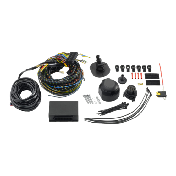
Wiringkit
D
Einbauanleitun g
Installation instructions
GB
F
Consignes de montage
NL
Montagehandleiding
Montagevejle dning
DK
N
Monter ingsinstruksjon
S
Installationsanvising
Asennusohje
FIN
I
Intruzioni per il montaggio
E
Instrucciones de montaje
Instuções de montagem
P
GR
Οδηγίες εγκατάστασης
CZ
Návod k montáži
Navodilo za vgradnjo
SLO
SK
Montážny návod
PL
Instrukcja montazu
Montaj talimatı
TR
H
Beépítési útmutató
HR
Upute o ugradnji
инструкции за монтаж
BUL
RO
Instruc iuni de montaj
RU
Инструкция по монтaжу и устaновке
Montavimo informacija
LT
LV
lemontešanas pamaciba
EST
Paigaldusjuhend
87040902 / 10.05.2017 /
Subject to changes
727617 19040531
MERCEDES BENZ
• A-Class W176
• B-Class W246
• CLA-Class C117
• CLA-Class X117 Shooting Brake
• GLA-Class X156
09/12
02/12
04/13
03/15
03/14
brink.eu
1/16
Advertisement

Related Manuals for Brink 727617


Summary of Contents for Brink 727617
- Page 1 Wiringkit 727617 19040531 Einbauanleitun g Installation instructions MERCEDES BENZ Consignes de montage Montagehandleiding • A-Class W176 09/12 Montagevejle dning • B-Class W246 02/12 Monter ingsinstruksjon • CLA-Class C117 04/13 Installationsanvising • CLA-Class X117 Shooting Brake 03/15 Asennusohje • GLA-Class X156...
- Page 2 Installation of the towing electrics kit must be undertaken by In case of missing a rear fog lamp on the trailer, it should be retrofitted. za specialist workshop or an appropriately qualified person. We accept no responsibility and give no guarantee for technical and electrical Before starting work, you must read the installation instruc- modifications made after the initial operation of the towing electrics kit by the tions through completely.
-
Page 3: Symbol Explanation
SYMBOL EXPLANATION left (58-L) respectively cigarette lighter / right (58-R) tail light accessory socket stop light (54) / loudspeaker / buzzer high mounted, third stop light (54) Park Distance Control turn signal indicator left turn signal indicator right switch / source of function Connect together rear fog light(s) Disconnect... - Page 4 ATTENTION! The vehicle's cooling capacity may have to be increased when retrofitting a trailer coupling! You must observe the manufacturer's instructions!! In order to avoid mal-functions and damage to the vehicle’s electrical system the earth terminal must be ATTENTION! disconnected from the vehicle’s battery before starting work! Both the trailer module and the vehicle’s control unit for the electrical system can be damaged during work on the data bus connections if the battery is not disconnected! Please pay attention to the manufacturer’s instructions when disconnecting and reconnecting the vehicle’s battery!
- Page 5 A-Class CLA-Class CLA-Class GLA-Class Shooting Brake B-Class 87040902 / 10.05.2017 / Subject to changes 5/16...
- Page 6 B-Class A-Class CLA-Class CLA-Class GLA-Class Shooting Brake B-Class B-Class 87040902 / 10.05.2017 / Subject to changes 6/16...
- Page 7 Belegung der Steckdose / Maximale Ausgangsleistung Socket configuration / Maximum power output ISO 1724 Correspondance des contacts de la prise / Puissance de sortie maxima Abbinamento della pr esa / Uscita di alimentazione massima Indeling van de stekker doos / maximaal uitgangsvermogen BK/WT 3/31 BK/GN...
- Page 8 Choose direction A-Class CLA-Class Shooting Brake B-Class 87040902 / 10.05.2017 / Subject to changes 8/16...
- Page 9 A-Class Option 1 Option 2 Important! Please note informations in picture 3! Option 1 Option 2 B-Class Important! Please note informations in picture 3! CLA-Class CLA-Class GLA-Class Shooting Brake Option 1 Option 2 Important! Please note informations in picture 3! GLA-Class MY 2017 YL/WT YL/WT...
- Page 10 CLA-Class CLA-Class GLA-Class MY2017 Shooting Brake A-Class B-Class BK/YL not required! RD/YL RD/BL CAN-Data wire Option 1 29 - 37 CAN-Data wire Option 2 38 - 39 Option 1 87040902 / 10.05.2017 / Subject to changes 10/16...
- Page 11 Option 1 Option 1 Option 1 Option 1 Option 1 Option 1 Option 1 CAN-Data Wire BR/RD 87040902 / 10.05.2017 / Subject to changes 11/16...
- Page 12 Option 1 2 PIN / BK 2 PIN / BK Important! Please note informations in picture 3! Option 2 Option 2 600 mm BR/RD CAN-Data Wire BR/RD BR/RD Important! Please note informations in picture 3! BR/RD 87040902 / 10.05.2017 / Subject to changes 12/16...
- Page 13 remove fuse box cover! RD/BL RD/YL RD/BL chamber 76 Open RD/YL chamber 77 secondary lock! 87040902 / 10.05.2017 / Subject to changes 13/16...
- Page 14 Close secondary lock! (RD/YL) (RD/BL) chamber 77 chamber 76 OPTIONAL everse BL/YL Supplementary harness everse 87040902 / 10.05.2017 / Subject to changes 14/16...
- Page 15 SETUP Ignition ON Optional: Adapter socket 768019 13-pin 7-pin OPTIONAL Trailer Simulator for 7- and 13-pin Sockets Part-no. 765069 90500542 Set up trailer operation The activation of the trailer functions has to be carried as follows: 1. Connect computer to car 11.
-
Page 16: Standby / Sleepmode
Diagnosis function of control LEDs Standby / No CAN-Data Sleepmode Ignition OFF Ignition ON Ignition ON PIN 13+14 CAN-Data Wire max 60 sec. Ignition ON /31: PIN 1 B+/30: PIN 2 oder/or 4 Ignition ON Indicator failure detection and lamp substitution if the trailer indicators fail The failure of a single or on both trailer indicators will be shown depending on the type of vehicle and electric kit installed as follows: •...
Need help?
Do you have a question about the 727617 and is the answer not in the manual?
Questions and answers