Advertisement
Quick Links
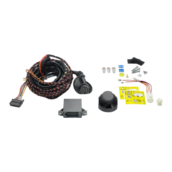
Wiringkit
D
Einbauanleitung
GB
Installation instructions
F
Consignes de montage
NL
Montagehandleiding
DK
Montagevejledning
N
Monteringsinstruksjon
S
Installationsanvising
FIN
Asennusohje
I
Intruzioni per il montaggio
E
Instrucciones de montaje
P
Instuções de montagem
GR
Οδηγίες εγκατάστασης
CZ
Návod k montáži
SLO
Navodilo za vgradnjo
SK
Montážny návod
PL
Instrukcja montazu
TR
Montaj talimatı
H
Beépítési útmutató
HR
Upute o ugradnji
BUL
инструкции за монтаж
RO
Instrucțiuni de montaj
RU
Инструкция по монтaжу и устaновке
LT
Montavimo informacija
LV
lemontešanas pamaciba
EST
Paigaldusjuhend
87271204 / 05.03.2019 /
Änderungen vorbehalten
756843
VW
• Tiguan II
• Tiguan II Allspace
04/16
09/17
brink.eu
Seite 1/28
Advertisement

Related Manuals for Brink 756843


Summary of Contents for Brink 756843
- Page 1 Wiringkit 756843 Einbauanleitung Installation instructions Consignes de montage Montagehandleiding Montagevejledning • Tiguan II 04/16 • Tiguan II Allspace 09/17 Monteringsinstruksjon Installationsanvising Asennusohje Intruzioni per il montaggio Instrucciones de montaje Instuções de montagem Οδηγίες εγκατάστασης Návod k montáži Navodilo za vgradnjo Montážny návod...
- Page 2 Der Einbau dieses Elektrosatzes muß von einer Fachwerkstatt Bei Anhängern ohne Nebelschlussleuchte sollte diese nachgerüstet werden. oder einer entsprechend qualifizierten Person durchgeführt werden. Vor Beginn aller Montagearbeiten unbedingt die Für technische bzw. elektronische Änderungen, welche nach erstmaliger Einbauanleitung komplett durchlesen. Nach Einbau des Elektrosatzes ist Inbetriebnahme des Elektrosatzes vom Fahrzeughersteller durchgeführt die Einbauanleitung den Serviceunterlagen des Fahrzeuges beizulegen! werden und beispielsweise zu Fehlfunktionen der Anhängersteckdose...
- Page 3 Pin-out Tools 10-15 22-42 7-8, 16-19 OPTION B OPTION A 87271204 / 05.03.2019 / Änderungen vorbehalten Seite 3/28...
- Page 4 Werkzeuge - Tools - Outils - Utensile - Herramientas - Werktuigen Tiguan II Tiguan II Allspace Anhänger-Vorbereitung! BK/VT 10-pin Ohne 6-pin Anhänger-Vorbereitung! ACHTUNG! ATTENTION! ATTENTION! ATTENZIONE! ¡ATENCION! ATTENTIE! Die Kühlerleistung des Fahr- The vehicle's cooling capacity peut s’avérer nécessaire La capacità di ra reddamento ¡Es posible que haya que koelvermogen zeuges muß...
- Page 5 Tiguan II 87271204 / 05.03.2019 / Änderungen vorbehalten Seite 5/28...
- Page 6 Tiguan II Allspace 87271204 / 05.03.2019 / Änderungen vorbehalten Seite 6/28...
- Page 7 Nur bei Fahrzeugen ohne Anhänger Vorbereitung Only for vehicles without trailer preparation 87271204 / 05.03.2019 / Änderungen vorbehalten Seite 7/28...
- Page 8 Nur bei Fahrzeugen ohne Anhänger Vorbereitung Only for vehicles without trailer preparation Tiguan II Tiguan II Allspace 87271204 / 05.03.2019 / Änderungen vorbehalten Seite 8/28...
- Page 9 Svart Black Schwarz Negro Noir Nero Preto Zwart Sort Svart Musta Cerná Fekete Czarny черный αύρο красный Rojo Rouge Rosso Vermelho Rood Rød Rød Röd Punainen Cervená Piros κόκκινο Czerwony зеленый Green Grün Verde Vert Verde Verde Groen Grøn Grønt Grön Vihreä...
- Page 10 Tiguan II Tiguan II Allspace Tiguan II Option 1 Option 2 Wichtig! Unbedingt Hinweise aus Bild 1 beachten! Important! Please note informations in picture 1! Tiguan II Allspace Option 1 Option 2 Wichtig! Unbedingt Hinweise aus Bild 1 beachten! Important! Please note informations in picture 1! 87271204 / 05.03.2019 /...
- Page 11 Tiguan II Tiguan II Allspace 21 - 22 43 - 62 23 - 62 BK/VT 10-pin 6-pin BK/VT 6-pin Pos. 28 = 15A Pos. 28 = 20A Pos. 38 = 20A Pos. 38 = 15A BK/VT 6-pin 87271204 / 05.03.2019 / Änderungen vorbehalten Seite 11/28...
- Page 12 OPTION 1 ontrol odule BCM-A 87271204 / 05.03.2019 / Änderungen vorbehalten Seite 12/28...
- Page 13 OPTION 1 BCM-A OR/BR OR/BR pin 17 pin 17 OR/GN OR/GN pin 16 OR/GN pin 16 OR/BR OR/GN pin 1 OR/BR pin 3 OPTION 1 BCM-C BCM-C BK/RD pin 2 BK/RD pin 58 BK/RD pin 58 87271204 / 05.03.2019 / Änderungen vorbehalten Seite 13/28...
- Page 14 OPTION 2 OR/BR OR/GN Wichtig! Unbedingt Hinweise aus Bild 1 beachten! OR/BR OR/BR Important! Please note informations OR/BR in picture 1! OR/GN CAN-Data Wire OR/BR (Kammer/ chamber 17) OR/GN OR/GN OR/GN OR/GN (Kammer / chamber 16) Bordnetzsteuergerät Steckgehäuse A Network control unit connector A OR/BR OR/GN...
- Page 15 OPTION 2 RD/YL B+/30 32 - 33 Option A 43 - 62 RD/BL B+/30 RD/YL 34 - 62 Option B RD/BL OPTION A Pos. 28 Pos. 38 OPTION A Wichtig! Die Sicherungsbrücke darf nicht in entgegengesetzter Richtung eingebaut werden! Important! Please do not mount the fuse tap and its wiring output in the other direction!
- Page 16 OPTION B RD/YL RD/BL OPTION B OPTION B AIRBAG 87271204 / 05.03.2019 / Änderungen vorbehalten Seite 16/28...
- Page 17 OPTION B AIRBAG Demontage Sicherungskasten OPTION B Remove Fusebox B+/30 Demontage Sicherungskasten OPTION B Remove Fusebox 87271204 / 05.03.2019 / Änderungen vorbehalten Seite 17/28...
- Page 18 Demontage Sicherungskasten OPTION B Remove Fusebox AIRBAG OPTION B RD/YL RD/BL Pos. 28 = RD/YL Pos. 38 = RD/BL OPTION B Pos. 28 = 15A Pos. 38 = 15A B+/30 87271204 / 05.03.2019 / Änderungen vorbehalten Seite 18/28...
- Page 19 OPTION 1 Codierung Steuergerät Seite 22-24 Code Control unit page 22-24 Codage dispositif de commande page 22-24 Codifica dispositivo di controllo pagina 22-24 Contralor de codificacion pagina 22-24 Bedieningsapparaat coderen pagina 22-24 SETUP Ignition ON 87271204 / 05.03.2019 / Änderungen vorbehalten Seite 19/28...
- Page 20 OPTION 2 Seite 25 page 25 page 25 pagina 25 pagina 25 pagina 25 Le seguenti funzioni per l’illuminazione Folgende Beleuchtungsfunktionen del rimorchio non sono supportate da tutte des Anhängers werden nicht bei allen Zugfahrzeugen le motrici con circuito di luci diurne: mit Tagesfahrlichtschaltung unterstützt: •...
- Page 21 Optional: Adapter socket 768019 7-pin 13-pin Anhängerbetrieb konfigurieren / Set up trailer operation Diagnosedienstleister bzw. Diagnosis Services or diagnostic Diagnostic services ou les méthodes Diagnosemethoden (lokal/o ine): methods (local / o ine): de diagnostic (local / hors ligne): • Hella Gutmann ( Seite 22) •...
- Page 22 Anhängerbetrieb konfigurieren / Set up trailer operation OPTION 1 Die Aktivierung der Anhängerfunktionen The activation of the trailer functions Pour activer l'attelage, procéder de la muss wie folgt durchgeführt werden: must be performed as follows: façon suivante : 1. Fahrzeugauswahl 1.
- Page 23 Anhängerbetrieb konfigurieren / Set up trailer operation OPTION 1 Codierung VW/Audi/Seat/Skoda mit VCDS Codage VW/Audi/Seat/Skoda avec VCDS Encoding VW/Audi/Seat/Skoda with VCDS Bitte beachten : Please note : Attention : Der nachfolgend beschriebene Ablauf zur Codierung The procedure described below for encoding and Le déroulement du codage et de l’activation du bzw.
- Page 24 Anhängerbetrieb konfigurieren / Set up trailer operation OPTION 1 Codering VW/Audi/Seat/Skoda met VCDS Codifica VW/Audi/Seat/Skoda con VCDS Codificación VW/Audi/Seat/Skoda con VCDS Gelieve in acht nemen : Attenzione : Atención : De hierna beschreven procedure voor de codering Il procedimento di codifica o abilitazione a esercizio El proceso de codificación y/o habilitación descrito a resp.
- Page 25 OPTION 2 Assistenzsysteme unterstützen den Anhängerbetrieb nicht OPTION 2 Pin 11 and Pin 2 disconnected Pin 11 and Pin 2 unterbrochen OPTION 2 OPTION 2 beep...beep OPTION 2 OPTION 2 87271204 / 05.03.2019 / Änderungen vorbehalten Seite 25/28...
- Page 26 max 60 sec. Follow the No CAN-Data instructions below Ignition ON CAN-Stecker/CAN-Connector BK / 2PIN 87271204 / 05.03.2019 / Änderungen vorbehalten Seite 26/28...
-
Page 27: Standby / Sleepmode
Diagnosefunktion der Kontroll-LED’s Diagnosis function of control LEDs Fonction diagnostic des LED de contrôle Funzione di diagnostica dei LED di controllo Función de diagnóstico de los LEDs de control Diagnosefunctie van de controle-LED´s Standby / No CAN-Data Sleepmode Ignition OFF Ignition ON Ignition ON PIN 13+14... - Page 28 87271204 / 05.03.2019 / Änderungen vorbehalten Seite 28/28...
Need help?
Do you have a question about the 756843 and is the answer not in the manual?
Questions and answers