Table of Contents
Advertisement
Advertisement
Table of Contents

Related Manuals for Labau TM200

Summary of Contents for Labau TM200
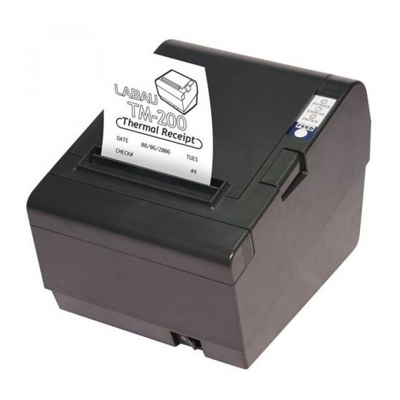
- Page 1 USER’S MANUAL THERMAL RECEIPT PRINTER...
- Page 2 This is a general guide for TM200 direct thermal printer, and not all functions will perform in every printer. Other than specified in this guide, for any special functions or specifications, please contact your dealer for details. Every effort is made to ensure the accuracy of our product information;...
-
Page 3: Table Of Contents
1. INTRODUCTION TABLE OF CONTENTS TM200 series printers are high-quality POS printers are designed for use with electronic instruments such as system ECR, POS, banking Introduction ........equipment, computer peripheral equipments. CHAPTER 1 SETTING UP THE PRINTER Unpacking .............. The printers have the following features: Connecting Cable........... -
Page 4: Chapter 1 Setting Up The Printer
Easy drop-in paper roll loading The illustration below shows the items should included for the standard of An auto-cutter is standard TM200 printer package. If any items are damaged or missing, please Support “partial” and “full” cutter. contact with your dealer for assistance. - Page 5 If the printer ahs a parallel interface, squeeze the wire clip on the printer together until they lock in place on both sides of the Connecting the Cables connector. Please connect up to four cables to the printer. They all connect to the Attach the other end of the cable to the computer.
- Page 6 Notes: Connecting the Power Supply Be sure to use paper rolls that meet the specifications. Do not WARNING: use paper rolls that have the paper glued to the core because the printer cannot detect the paper end correctly. Make sure that you use the optional +24V power supply or equivalent for your printer.
- Page 7 Insert the paper roll as shown. Pull out a small amount of paper, as shown. Then close the cover. Be sure to note the correct direction that the paper comes off 7. Tear off the paper as shown. the roll.
-
Page 8: Adjustments And Settings
Adjustments and Settings Using the Printer The TM200 Series are set up at the factory to be appropriate for You can control the basic paper feeding operations of the printer with almost all users. It does, however, offer some settings for users the button on the control panel. -
Page 9: Chapter 2 The Self Test
Indicator on Control Panel Chapter 2. The self test The self test lets you know if your printer is operating properly. It checks Status Description the control circuits, printer mechanisms, print quality, ROM version, and Printer power is on. Power light “On” DIP switch settings. -
Page 10: Chapter 3 Reference Information
Chapter 3. Reference Information Standard Double-height Printing Specifications Printing method: Thermal line printing W x H (mm) W x H (mm) Dot density: 203 dpi x 203 dpi (8 dot/mm) Font A 1.23 x 2.97 1.23 x 5.92 Printing direction: Unidirectional with friction feed 12 x 24 (.05”... -
Page 11: Paper Specifications
Paper Specifications Reliability Mechanism: 15,000,000 lines Size: Width: 80.0mm+0.5mm Thermal (3.15” + 0.02”) 100 million pulses, 50 km head: Maximum outside Life: 83 mm (3.27”) Auto cutter: 1,200,000 cuts diameter: (End of Life is defined to have reached the end of its Paper roll spool Inside: 12mm (0.47”) Paper roll... -
Page 12: Chapter 4 Troubleshooting
Chapter 4. Troubleshooting This chapter gives solutions to some printer problems you may have General problems ※ The lights on the control panel do not come on. Make sure that the power supply cables are correctly plugged into the printer, the power unit, and to the power outlet. Make sure that power is supplied to the power outlet. -
Page 13: Cleaning The Print Head
※ If the PAPER “Red” light is blinking, Cleaning the print head The paper roll is not installed or is at or near the end. Install a new paper roll. See Chapter 1 for instructions. CAUTION: After printing, the print head can be very hot. Be careful not to touch it. ※... -
Page 14: Auto Cutter Problems
4. Then turn the knob until you see cutter blade back to the lowest Pull the cutter cover toward you so that you can rotate the position, as shown in the illustration below. This returns the cutter motor knob. cutter blade to the normal position. Also notice that there is a label near the cutter to assist you. -
Page 15: Hexadecimal Dump
Hexadecimal Dump Function 1B 21 00 1B 26 02 40 40 ← ! ← & ☻ @ @ Print emulation TM200 EPSON Emulation 1B 25 01 1B 63 34 00 1B ←%☺← c 4 ← Paper near end sensor Vertical... - Page 16 Print Density Selection Set 2 Function Print Density SW 1-3 SW 1-4 1 Low power consumption mode Data receive error Ignored Prints “?” 2 (Normal) Receive buffer 80K bytes 2K bytes capacity 4 (Dark) Handshaking XON / XOFF DTR / DSR Data word length 7 bits 8 bits...
- Page 17 Print Density Selection Set 1 Print Density SW 1- 3 SW 1- 4 Function 1 Low power consumption Print emulation TM200 EPSON Emulation mode Paper near end sensor Vertical Horizontal 2 (Normal) Selects print density Refer to page “A-5” table...
-
Page 18: Appendix B Connectors
Turn off the printer while removing the DIP switch cover to prevent an electric short, which can damage the printer. Make sure the printer is turned off. TM200 Connector (Serial interface) Remove the screw from the DIP switch cover. Then take off the DIP switch cover, as sown in the illustration below. - Page 19 Parallel Interface (IEEE-1284) Drawer Connector Compatibility Source Nibble Mode Byte Mode Pin No. Signal name Direction mode Frame ground Host nStrobe HostClk HostClk Drawer kick-out drive signal 1 Output Host Printer Data 0 (LSB) Data 0(LSB) Drawer open/close signal Input Data 1 Data 1 Host...
Need help?
Do you have a question about the TM200 and is the answer not in the manual?
Questions and answers