Table of Contents
Advertisement
Quick Links
CT
MANUAL • HANDBUCH • MANUEL
T
B
:
5
0
0
m
s
D
t
:
1
0
0
n
s
S
CH1:=100mV CH2 :~100mV CHP
0.2 Vpp
CAL.
CURSOR
I/II
∆V
1kHz
TRK
∆t
1MHz
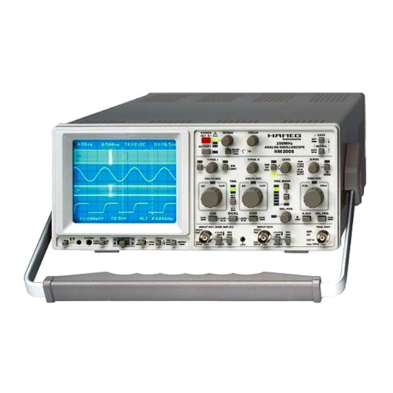
Oscilloscope
POWER
!
A
RO
R
5
B
AUTOSET
RM
Y -POS. I
TRS
VOLTS / DIV.
VAR
5V
CH I
VAR.
INPUT CH I (HOR. INP .(X))
1MΩ II
15pF
x1/x10
!
CH I/II
1
ON
max.
∆t
MENU
OFF
250 Vp
AC/DC
HM 2005
INTENS
FOCUS
Instruments
200 MHz
ANALOG OSCILLOSCOPE
READ
HM2005
TR
OUT
Y -POS. II
LEVEL
BWL
NM
NM
BW
AT
LIMIT
TR
VOLTS / DIV.
TRIG. MODE
TRIG.
VAR
1mV
5V
1mV
CHI
AC
CHII
DC
EXT
HF
NR
ALT
LF
TVL
TVF
DEL.POS.
X-Y
DUAL
CH II
HO
CHP .
ADD
VAR.
CAT
I
INPUT CH II
1MΩ II
15pF
x1/x10
INV.
!
max.
GD
250 Vp
AC/DC
SAVE
SET
9
RECALL
1
EXIT
X-POS.
x10
PUSH
LONG
PUSH
X-
BOTH
MAG.
TIME / DIV.
VAR
0.5s
20ns
A/ALT.
DEL.TRIG
B
VAR.
TRIG. EXT. INP
(Z)
INV.
!
max.
100 Vp
GD
Advertisement
Table of Contents

Related Manuals for Hameg HM 2005


Summary of Contents for Hameg HM 2005
- Page 1 Oscilloscope HM 2005 POWER INTENS FOCUS SAVE Instruments 200 MHz AUTOSET RECALL ANALOG OSCILLOSCOPE READ HM2005 EXIT Y -POS. I Y -POS. II LEVEL X-POS. PUSH LONG LIMIT PUSH BOTH MAG. VOLTS / DIV. VOLTS / DIV. TIME / DIV.
- Page 2 M A N U A L • H A N D B U C H • M A N U E L Subject to change without notice...
-
Page 3: Table Of Contents
Table of contents Oscilloscope HM 2005 General information regarding the CE marking ..... Triggering and Time Base ..........Specifications HM2005 ............. Automatic Peak (value) -Triggering ......... Important hints ..............Normal Triggering ............Useof tilt handle ............. - Slope ..............Safety ................ -
Page 4: General Information Regarding The Ce Marking
General information regarding the CE marking HAMEG instruments fulfill the regulations of the EMC directive. The conformity test made by HAMEG is based on the actual generic- and product standards. In cases where different limit values are applicable, HAMEG applies the severer standard. For emission the limits for residential, commercial and light industry are applied. -
Page 5: Specifications Hm2005
The built in RS-232 serial interface permits remote controlled operation by a X-Y phase shift: <3° below 220kHz PC. The outstanding feature of the HM 2005 include a second time base with the Operation / Control ability to magnify, over 1000 times, extremely small portions of the input signal. -
Page 6: Important Hints
Important hints Important hints The case, chassis and all measuring terminals are connected to the protective earth contact of the appliance inlet. The instrument operates according to Safety Class I (three conductor power cord This oscilloscope is easy to operate. The logical arrangement of with protective earthing conductor and a plug with earthing the controls allows anyone to quickly become familiar with the contact). -
Page 7: Emc
+10°C (+50°F) ... the technical data are based. Purchase of the HAMEG scope +40°C (+104°F). It may occasionally be subjected to temperatures tester HZ 60, which despite its low price is highly suitable for between +10°C (+50°F) and -10°C (+14°F) without degrading its... -
Page 8: Basics Of Signal Voltage
Basics of signal voltage Basics of signal voltage to-peak value must be divided by 2x√2 = 2.83. Conversely, it should be observed that sinusoidal voltages indicated in Vrms (Veff) have 2.83 times the potential difference in Vpp. The relationship between the different voltage magnitudes can be Type of signal voltage seen from the following figure. -
Page 9: Total Value Of Input Voltage
For sine wave signals with frequencies higher than 40Hz this influence is negligible. With the above listed exceptions HAMEG 10:1 probes can be used for DC measurements up to 600V or AC voltages (with a With the designations mean value of zero volt) of 1200Vpp. -
Page 10: Connection Of Test Signal
Basics of signal voltage When very fast rise times are being measured, the rise times of required period T = 7x100x10 -9 = 0.7µs the oscilloscope amplifier and of the attenuator probe has to be required rec. freq. F = 1:(0.7x10 -6 ) = 1.428MHz. deducted from the measured time value. -
Page 11: Controls And Readout
During this time voltage rating is max. 250 V (DC + peak AC). DC input the HAMEG logo and the software version are displayed on coupling is therefore of quite special importance with a the screen. After the internal test is completed successfully,... - Page 12 Controls and Readout Even if alternating time base mode or B time base mode was active before, the instrument is switched automatically POWER INTENS FOCUS to A time base mode. Please note “AUTOSET” . SAVE Instruments 200 MHz Automatic CURSOR supported voltage measurement. If RECALL AUTOSET ANALOG OSCILLOSCOPE...
- Page 13 Controls and Readout Consequently this function is only available in alternate time (10) BW Limit – Pushbutton with associated BWL-LED. base mode. After the TRS pushbutton was pressed once the LED related to that pushbutton is lit. Pressing this pushbutton switches the BWL–LED and readout display on or off.
- Page 14 Controls and Readout 3. The peak value detection is switched off if the trigger point (16)X-MAG. x10 – Pushbutton and LED. can be set outside the maximum peak values of the signal, Each time this pushbutton is pressed the x10 LED located thus causing an untriggered signal display.
- Page 15 Controls and Readout coefficient into calibrated condition and activates the XY mode: attenuator function. The previous vernier setting will not be This mode can be switched on or off by pressing and holding stored. the DUAL button (19). The CHI pushbutton can also be pressed simultaneously with the DUAL(19) button.
- Page 16 Controls and Readout The deflection coefficients and additional information In some trigger modes such as alternate triggering, some trigger regarding the active channels are displayed in the readout, coupling modes are automatically disabled and can not be e.g. “Y2: deflection coefficient, input coupling” . The “:” selected.
- Page 17 Controls and Readout 20ms/div up to 20ns/div (without X-MAG. x10) but the the start of the A time base trace and the beginning of the availability depends on the A time base setting. The internal intensified sector shows the delay time. This information is control of the oscilloscope prevents the B time deflection also displayed in the readout as an approximative value (e.g.
- Page 18 Controls and Readout and slope can be set independently using the same controls (29)AC / DC – Pushbutton with two functions. used for the A time base trigger setting. The trigger point is indicated again but has the added letter B in the readout. Input coupling: Briefly pressing this pushbutton switches over from AC (~ In delay trigger mode, the delay time must first elapse.
- Page 19 Controls and Readout Below the CRT there are the controls for the readout, the Probe factor: component tester and the square wave calibrator with their Pressing and holding the pushbutton selects the indicated outputs. deflection coefficient of channel II displayed in the readout, between 1:1 and 10:1.
- Page 20 Controls and Readout calibrated. The settings of the cursors must relate to the signal (10:1) probes, the probe factor can be automatically included of the selected channel. (see item (29) and (33)). If a x100 (100:1) probe is used, switch to the probe symbol In XY-mode the instrument is automatically set to ∆...
-
Page 21: Menu
Menu 1.2.1.3 QUICK START ON/OFF In condition ON the HAMEG logo and the menus will not be The instrument software contains a menu and submenus. The displayed after switching the instrument on. Then the instrument menu allows changes to the default settings regarding the is quickly ready for operation. -
Page 22: First Time Operation
The oscilloscope is switched on by depressing the red POWER reproduction of non-sinusoidal high frequency signals. pushbutton. After a few seconds the HAMEG logo and the instrument software release is displayed on the screen. As long as Adjustment at 1kHz the HAMEG logo is visible different internal checks are made. -
Page 23: Adjustment At 1Mhz
Operating modes 0.2ms/div. All deflection coefficients should be calibrated. Plug it should be pointed out that most of these probes have a slower the probe tip into the calibrator output socket. rise time with the effect that the total bandwidth of scope Approximately 2 complete waveform periods are displayed on together with probe may fall far below that of the oscilloscope. -
Page 24: X-Y Operation
Operating modes In-phase input voltages: Calculation of the phase angle or the phase shift between the X No invert function active = sum. and Y input voltages (after measuring the distances a and b on One invert function active = difference. the screen) is quite simple with the following formula, and a Both invert functions (if available) active = sum. -
Page 25: Measurement Of Amplitude Modulation
Triggering und Time Base Phase difference measurement in DUAL mode t = horizontal spacing of the zero transitions in div T = horizontal spacing for one period in div Figure 2 Amplitude modulated oscillation: F = 1 MHz; f = 1 kHz; m = 50 %; UT = 28.3 mVrms. In the example illustrated, t = 3div and T = 10div. -
Page 26: Automatic Peak (Value) -Triggering
Triggering and Time Base threshold can be stated as vertical display height in div, at which When using the internal normal triggering mode, it is possible to the time base generator starts, the display is stable, and the trigger at any amplitude point of a signal edge, even with very trigger indicator LED lights or flashes. -
Page 27: Triggering Of Video Signals
Triggering and Time Base In this coupling mode the transmission range equals a TVL: On the 10µs/div setting and line TV triggering selected, high pass filter. It cuts off the DC content of the trigger approx. 1½ lines are visible. Those lines originate from signal and the lower frequency range. -
Page 28: External Triggering
Triggering and Time Base met ( please note “Controls and Readout” ). In the case of signal frequencies. The indication pulses are of only 100ms chopped DUAL mode, selecting alternate trigger mode duration. automatically sets the instrument to alternate DUAL mode. The trigger point symbol and the peak value detection (in automatic Thus for fast signals the LED appears to glow continuously, for trigger mode) are internally deactivated. -
Page 29: B-Time Base (2Nd Time Base)/ Triggering After Delay
AUTOSET AUTOSET amplitudes. Only a very exact trigger level adjustment makes a single display possible. The use of the holdoff control simplifies the right adjustment. The instrument specific information regarding this function is part After specific use the holdoff control should be reset into its of the section “Controls and Readout”... -
Page 30: Main Value Display
Mean Value Display In such cases it is recommended to select normal triggering and capacitors, and inductors. Certain tests can also be made to to set the trigger point approx. 0.5div above or below the trace. integrated circuits. All these components can be tested If under one of these conditions the trigger indicator LED is lit, individually, or in circuit provided that it is unpowered. -
Page 31: Testing Semiconductors
Component Texter Testing Transistors giving an ellipse-shaped display. The position and opening width of the ellipse will vary according to the impedance value (at 50Hz) Three different tests can be made to transistors: base-emitter, of the component under test. base-collector and emitter-collector. The resulting test patterns are shown below. -
Page 32: Adjustments
Measurement on a high level reference potential is not permitted and endangers operator, oscilloscope, interface and peripheral devices. In case of disregard of the safety warnings contained in this manual, HAMEG refuses any liability regarding personal injury and/or damage of equipment. Operation The oscilloscope is supplied with a serial interface for control purposes. -
Page 33: Subject To Change Without Notice
RS-232 Interface The only ways to quit this status are: Switching the oscilloscope off, transmitting the command RM= 0 from the PC to the oscilloscope, or depressing the AUTOSET ( LOCAL ) pushbutton, if in unlocked condition (command LK=1... was not sent) After the remote state has been switched off the RM -LED (3) is dark. -
Page 34: Front Panel Hm2005
Front panel HM 2005 Subject to change without notice... - Page 35 M A N U A L • H A N D B U C H • M A N U E L Subject to change without notice...
-
Page 36: Power Supplies
Oscilloscopes Multimeters Counters Frequency Synthesizers Generators R- and LC-Meters Spectrum Analyzers Power Supplies Curve Tracers Time Standards HAMEG GmbH Industriestraße 6 D-63533 Mainhausen Telefon: (0 61 82) 800-0 Telefax: (0 61 82) 800-100 E-mail: sales@hameg.de Internet: www.hameg.de Printed in Germany...
Need help?
Do you have a question about the HM 2005 and is the answer not in the manual?
Questions and answers