Table of Contents
Advertisement
TMG Corporate Website
Disclaimer:
All trademarks appearing within this PDF are trademarks of their respective owners.
Form 080/01
Complimentary Reference Material
This PDF has been made available as a complimentary service for you to assist in
evaluating this model for your testing requirements.
TMG offers a wide range of test equipment solutions, from renting short to long
term, buying refurbished and purchasing new. Financing options, such as
Financial Rental, and Leasing are also available on application.
TMG will assist if you are unsure whether this model will suit your requirements.
Call TMG if you need to organise repair and/or calibrate your unit.
If you click on the "Click-to-Call" logo below, you can all us for FREE!
TMG Products Website
Advertisement
Table of Contents

Related Manuals for Hameg HM504-2


Summary of Contents for Hameg HM504-2
- Page 1 Complimentary Reference Material This PDF has been made available as a complimentary service for you to assist in evaluating this model for your testing requirements. TMG offers a wide range of test equipment solutions, from renting short to long term, buying refurbished and purchasing new. Financing options, such as Financial Rental, and Leasing are also available on application.
- Page 3 O s c i l l o s c o p e H M 5 0 4 - 2 Manual English...
-
Page 4: Table Of Contents
RS-232 protocol ..............35 External triggering ............29 Baud-Rate Setting ............35 Trigger indicator ”TR” ............30 Data Communication ............35 HOLD OFF-time adjustment ..........30 Delay / After Delay Triggering ........... 30 Front Panel HM504-2 ............36 Subject to change without notice... -
Page 5: Ce-Declaration Of Conformity
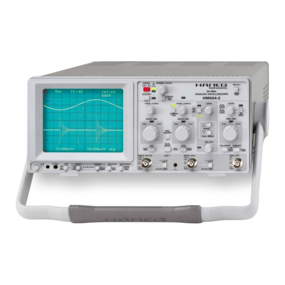
General information regarding the CE marking HAMEG instruments fulfi ll the regulations of the EMC directive. The conformity test made by HAMEG is based on the actual generic- and product standards. In cases where different limit values are applicable, HAMEG applies the severer standard. - Page 6 HM504-2 5 0 M H z A n a l o g O s c i l l o s c o p e H M 5 0 4 - 2 Full screen display of 50 MHz sine wave 2 Channels with deflection coefficients of 1 mV/cm – 20 V/cm Time Base: 0.5 s/cm –...
-
Page 7: Specifications
HM504-2E/140408/ce · Subject to alterations · © HAMEG Instruments GmbH · ® Registered Trademark · DQS-certified in accordance with DIN EN ISO 9001:2000, Reg.-No.: DE-071040 QM HAMEG Instruments GmbH · Industriestr. 6 · D-63533 Mainhausen · Tel +49 (0) 6182 800 0 · Fax +49 (0) 6182 800 100 · www.hameg.com · info@hameg.com A Rohde &... -
Page 8: General Information
PUkT PUOPFGkT PUOPFGkT PUkT PUkT PUkT INPUT CHI PUkT INPUT CHI INPUT CHI HAMEG PUkT placed on a table). Then the handle locking knobs PUOPFGkT PUOPFGkT HJKL HJKL HJKL must be simultaneously pulled outwards and STOP rotated to the required position. Without pulling the locking knobs they will latch in into the next locking position. -
Page 9: Emc
Transients are short, very fast voltage or current excursions which may be periodic or not. Return material authorization (RMA): Prior to returning an instrument to HAMEG ask for a RMA number Measurement CAT IV: either by internet (http://www.hameg.com) or fax. If you do not Measurements close to the power station, e.g. -
Page 10: Type Of Signal Voltage
Type of signal voltage Type of signal voltage The oscilloscope HM504-2 allows examination of DC voltages and most repetitive signals in the frequency range up to at least 50 MHz (–3 dB). The Y amplifiers have been designed for minimum overshoot and therefore permit a true signal display. -
Page 11: Total Value Of Input Voltage
2.5 is reached. Therefore any intermediate value is possible within the 1-2-5 sequence. Apart from the above listed exceptions, HAMEG 10:1 probes can be used for DC measurements up to 600 V or AC voltages (with With the designations a mean value of zero volt) of 1200 V . -
Page 12: Rise Time Measurement
Type of signal voltage With a time coefficient of 10 ns/div (X x10 magnification active), Examples: the example shown in the above figure results in a total measured Displayed wavelength L = 7 div, risetime of set time coefficient Tc = 100 ns/div, thus period T = 7 x 100 x 10 = 0.7 µs = 1.6 div x 10 ns/div = 16 ns... -
Page 13: Controls And Readout
HZ34, a 50 Ohm through termination type HZ22 is available BNC-socket, a BNC adapter should be used. In this way ground from HAMEG. When transmitting square signals with short rise and matching problems are eliminated. Hum or interference times, transient phenomena on the edges and top of the signal appearing in the measuring circuit (especially when a small may become visible if the correct termination is not used. -
Page 14: B: Readout Information
“A”: Description of Controls The INTENS/FOCUS control knob adjusts the signal(s) The large front panel is, as usual with Hameg oscilloscopes, intensity. Turning this knob clockwise increases the intensity. marked with several fields. Only the minimum required trace intensity should be used,... - Page 15 17 19 50 MHz SAVE AUTOSET ANALOG OSCILLOSCOPE TRACE HM504-2 [6] Y-POS/CURS. I – Control knob with two functions. ROT. This knob allows position control of channel I trace or CUR- SOR line(s). Briefly pressing the CURSOR POS pushbutton [4] RM [7] selects the function.
- Page 16 Controls and Readout [7] CURSOR POS – Pushbutton and LED. If addition mode (“add”) is present just one ”^” symbol is Briefly pressing this pushbutton determines the function of visible. the Y-POS/CURS.I [6] and Y-POS/CURS.II [8] controls. In XY mode the “0 Volt” trace position for channel I (X) and If the LED is not lit the Y position control function is active.
- Page 17 Controls and Readout mode. Whether the LED flashes or is lit constantly depends [15] CH I VAR. – Pushbutton with two functions. on the frequency of the trigger signal. Pressing and holding this pushbutton selects the VOLTS/ DIV. [14] control knob function between attenuator and [11] LEVEL –...
- Page 18 Controls and Readout base setting, but can be changed in the pulldown menu. The the signal used for triggering originates. The measuring oscilloscope automatically determines the channel switching amplifiers (internal triggering) or the BNC socket which mode after a change of the time base setting. serves as an input for externally applied signals (external triggering) can be used as a trigger source.
- Page 19 Controls and Readout coefficient) if turned in the opposite direction (ccw.). The available range is from 1mV/div up to 20V/div. Y -POS / CURS.I Y -POS / CURS.II LEVEL X-POS. The deflection coefficients and additional information PUSH BOTH regarding the active channel(s) are displayed in the readout, PUSH LONG CURSOR...
- Page 20 Controls and Readout Readout (e.g. “10 µs”). Depending on the time base mode Functions the following ranges are available without taking X x10 into account. “sea”: In SEARCH mode, the holdoff time is automatically set to Undelayed: 500 ms/div – 50 ns/div. minimum and for the first few divisions the trace is blanked.
- Page 21 Controls and Readout The current function is indicated by the VAR LED. The TIME/ [28] INPUT CH II – BNC socket. DIV. knob functions as a vernier when the VAR LED is This BNC socket is the signal input for channel II. The outer switched on, but the time base setting remains calibrated (ground) connection is galvanically connected to the until the (vernier) knob is operated.
- Page 22 Controls and Readout [31] MAIN MENU – READOUT – Pushbutton with double For voltage measurement, AC or DC trigger coupling is function. required. DC voltage measurement assumes DC input coupling. MAIN MENU In the case of high frequency signals, the different frequency Briefly pressing calls the MAIN MENU.
- Page 23 Controls and Readout 1/∆ ∆ ∆ ∆ ∆ t (display “1/∆t: measured value“) The unit to be displayed must be selected by briefly pressing Two vertical CURSOR lines enable frequency measurement the UNIT [35] pushbutton to call the UNIT menu. Then the in Yt mode (not in XY mode).
- Page 24 Controls and Readout Gain (display “gain: measured value, unit”) “∆V“ and “V to GND“) two long CURSOR lines are Ratio measurement of signal voltages by the aid of two long displayed. Briefly pressing SOURCE selects the channel and two short CURSOR lines; enabled only in Yt (time base) and it`s deflection coefficient for the measurement.
-
Page 25: Menu
1.1.3 TRIGGER AMP 2.1.3 QUICK START. Reduces the waiting time after POWER 1.1.4 X MAG POS ON, as neither the HAMEG logo nor the check and 1.1.5 CT X POS initialisation are displayed. Calling one of these menu items requires that no signal is applied FACTORY on any input. -
Page 26: First Time Operation
As long as the HAMEG logo is visible different internal checks are made. Thereafter the instrument will revert to Adjustment at 1 kHz its last used operating mode. -
Page 27: Operating Modes Of The Vertical Amplifiers In Yt Mode
Operating modes oft the Y amplifiers in Yt mode Prerequisite for this HF compensation is a square wave generator Operating modes with fast risetime (typically 4 ns), and low output impedance of the Y amplifiers in Yt mode (approx. 50 Ohm), providing 0.2 V at a frequency of approx. 1MHz. The calibrator output of this instrument meets these requirements. -
Page 28: Phase Comparison With Lissajous Figures
Operating modes oft the Y amplifiers in Yt mode Phase difference measurement The bandwidth of the X amplifier, is lower than the Y amplifier in DUAL mode (Yt) and the phase angle which increases with higher frequencies, must be taken into account (please note data sheet). Phase differences between two input signals of the same frequency and shape can be measured very simply on the screen The Y signal applied at INPUT CHII can be inverted. -
Page 29: Triggering And Time Base
Triggering and time base base generator moves the beam from the left to the right of the screen (time deflection = t). Normally there are periodically repeating waveforms to be displayed. Therefore the time base must repeat the time deflection periodically too. -
Page 30: Normal Triggering
Triggering and time base The automatic peak (value) triggering operates over all variations As the automatic triggering does not work below 20 Hz, normal or fluctuations of the test signal above 20 Hz. However, if the triggering should be used in DC and LF trigger coupling mode. The pulse duty factor of a square wave signal exceeds a ratio of coupling mode and accordingly the frequency range of the trigger 100 : 1, switching over to normal triggering will be necessary. -
Page 31: Line/Mains Triggering (~)
Triggering and time base positive going edges must be chosen. In the case of sync pulses In this trigger mode the slope direction pushbutton selects the below the field/line, the leading edge is negative and consequently positive or negative portion of the line/mains sine wave. The the slope selection must be set for falling edges. -
Page 32: Trigger Indicator "Tr
Triggering and time base form from the test signal voltage, but must be synchronous with the test signal. Triggering is even possible in certain limits with whole number multiples or fractions of the test frequency. It must be noted that a different phase angle between the measuring and the triggering signal may cause a display not coinciding with the slope selection setting. - Page 33 Triggering and time base The following explanation assumes that the trace starts on the Please note that the previous time coefficient chosen in “del” left vertical graticule line. and “dTr” mode is stored and automatically set after activating one of those modes. If the stored time coefficient in “del” / Photo 1 ”dTr”...
-
Page 34: Autoset
AUTOSET X x10 magnifier switched off The manipulation of time delay requires a certain experience, Optimum X and Y position settings especially with complicated signal combinations which are Trace and readout visible. difficult to display. The display of sections of simple signals is, in contrast, fairly easy. -
Page 35: Component Tester
Component Tester Test Pattern Displays reality, other deviations such as unavoidable offset voltages must be taken into account, which may cause a display deviating from The following ”Test patterns” show typical patterns displayed by 0 Volt without signal applied at the input. the various components under test. -
Page 36: Testing Diodes
AUTOSET Testing Diodes In-Circuit Tests Diodes normally show at least their knee in the forward characteristic. This is not valid for some high voltage diode types, Caution! because they contain a series connection of several diodes. During in circuit tests make sure the circuit is dead. No power from mains/line or battery and no signal inputs are permitted. -
Page 37: Adjustments
In case of disregard of the safety warnings contained in this A CompactDisc with programming examples, a command list manual, HAMEG refuses any liability regarding personal injury and a program executable under Windows 95, 98, Me, 2000, NT and/or damage of equipment. -
Page 38: Front Panel Hm504-2
Front Panel HM504-2 Subject to change without notice... - Page 39 Front Panel HM504-2 Subject to change without notice...
- Page 41 LEER...
- Page 42 . h a m e g . c o m Subject to change without notice 41-0504-02E1 / 11082008-gw HAMEG Instruments GmbH © HAMEG Instruments GmbH Industriestraße 6 A Rohde & Schwarz Company D-63533 Mainhausen ® registrierte Marke Tel +49 (0) 61 82 800-0 DQS-Zertifi...
Need help?
Do you have a question about the HM504-2 and is the answer not in the manual?
Questions and answers