Table of Contents
Advertisement
Quick Links
Advertisement
Table of Contents

Related Manuals for VIRTUFIT Indoor Cycle S1 Spinbike


Summary of Contents for VIRTUFIT Indoor Cycle S1 Spinbike
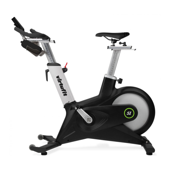
- Page 1 Indoor Cycle S1 Spinbike User manual...
- Page 2 11 - 12 ADJUSTMENTS GUIDE ADJUSTMENTS GUIDE MAINTENANCE MAINTENANCE TROUBLE SHOOTING TROUBLE SHOOTING 15 - 16 CONTROL PANEL CONTROL PANEL EXPLODED DRAWING EXPLODED DRAWING 18 - 19 PARTS LIST PARTS LIST TRAINING INSTRUCTIONS TRAINING INSTRUCTIONS VirtuFit Indoor Cycle S1 Spinbike...
-
Page 3: Safety Instructions
– Ensure there are no children nearby when you are exercising on the device. In addition, the device should be showed in a place that children or house pets cannot reach. – Ensure that only one person at a time uses the fitness device. Virtufit Indoor Cycle S1 Spinbike... - Page 4 – Maintenance assembly and repair work not carried out by an official dealer. – In the event of improper use, neglect and / or poor maintenance. – Failure to maintain the fitness equipment in accordance with the manufacturer’s instructions (see the enclosed manual). VirtuFit Indoor Cycle S1 Spinbike...
- Page 5 (4 mm) Semicircular head cross Inner hexagon wrench (5 mm) flower screw M5*16 Inner hexagon wrench Semicircular head cross (6 mm) flower screw M5*20 Semicircular head inner Inner hexagon wrench hexagon screw M10*60 (8 mm) Virtufit Indoor Cycle S1 Spinbike...
- Page 6 In this way you prevent the head of the socket head screw from being rotated. STEP 1 • Use the hexagon screw M10 * 60 (A1), washer ø10 (A2), locknut M10 (A4) to attach the front (5) and rear (6) stabilizer to the frame (1). VirtuFit Indoor Cycle S1 Spinbike...
- Page 7 ASSEMBLY INSTRUCTIONS STEP 2 • Place the handlebar (8) in the frame (1) and make sure that you adjust it to the correct height. Then connect the wires. Virtufit Indoor Cycle S1 Spinbike...
- Page 8 Place the steering rod (8) in the position as shown in the figure. Use the countersunk head screw M8*16 to attach the handlebar (7) to the handlebar (8). Pay attention! This hex screw is already attached to the steering rod (8). VirtuFit Indoor Cycle S1 Spinbike...
- Page 9 The pedals are marked with “L” (Left) and “R” (Right). Connect them to their correct crank. The judge crank is on the right side of the bicycle when you sit down. Note that the right pedal must are attached clockwise and the left pedal counterclockwise. Virtufit Indoor Cycle S1 Spinbike...
- Page 10 Place the seat post (9) in the frame (1) and make sure that you adjust it to the correct height. Then confirm the saddle (4) on the seat post (9). • Check that all parts / screws are correctly attached and without play. So prevents parts from coming loose. VirtuFit Indoor Cycle S1 Spinbike...
- Page 11 FIGURE 6 FIGURE 7 NOTE: When adjusting the upper and lower positions of the handle and the seat, their highest position should not exceed the horizontal “STOP” line as shown in Figure 8. FIGURE 8 Virtufit Indoor Cycle S1 Spinbike...
-
Page 12: Adjusting The Balance
If you want to stop button for an training, you can adjust console to increase resistance or emergency stop press directly the brakes resistance regulator down until FIGURE 12 crank stops, and then trainer can get off the bike. VirtuFit Indoor Cycle S1 Spinbike... -
Page 13: Daily Maintenance
The batteries must be installed correctly. If the screen is unreadable or only parts of the image work, follow the next step: Remove the batteries and wait 15 seconds, then reinsert the batteries correctly. Virtufit Indoor Cycle S1 Spinbike... -
Page 14: Troubleshooting
Tighten the pedals firmly. Should this not be the case offer a solution, report this to the supplier. The console is not working If there is no signal when pedaling, check that the cable is properly attached. VirtuFit Indoor Cycle S1 Spinbike... -
Page 15: Control Panel
If you press the RESET button once to reset the function you are currently using. RESET Hold down the RESET button to reset all functions at once. RECOVERY Heart Rate Recovery Test. Virtufit Indoor Cycle S1 Spinbike... - Page 16 F1 to F6. In this way the recovery capacity of your heart tested. On below schedule you can view your Below average recovery capacity. Poor • If you press RECOVERY again, you will return to the get started. VirtuFit Indoor Cycle S1 Spinbike...
-
Page 17: Exploded Drawing
EXPLODED DRAWING Exploded View Virtufit Indoor Cycle S1 Spinbike... - Page 18 Left shell Front axle Right shell Knob Outer shell round cover Semicircular head inner hexagonal screws Semicircular head cross flower self- M10*60 tapping screw ST4*16 Washer Ø10 Semicircular head cross flower screw M4*12 Spring washer Ø10 VirtuFit Indoor Cycle S1 Spinbike...
- Page 19 Semicircular head ineer hex screw M12*40 Deep groove ball bearing Non-slip nut M10 Console connecting line Strong magnetic Ø25*T8 Cylindrical head inner hex screw M5*30 Non-slip nut M5 Cylindrical head inner hex screw M10*20 Spring washer Ø10 Virtufit Indoor Cycle S1 Spinbike...
-
Page 20: Training Instructions
The purpose of cooling down is to return the body to its normal or near normal, resting state at the end of each exercise session. A proper cool-down slowly lowers your heart rate and allows blood to return to the heart. VirtuFit Indoor Cycle S1 Spinbike... - Page 21 For questions or missing parts please contact your dealer.
Need help?
Do you have a question about the Indoor Cycle S1 Spinbike and is the answer not in the manual?
Questions and answers