Table of Contents
Advertisement
Eskimo Ice Crushed Ice System
Installation & Operation Manual
F
M
EI540D
OR
ODEL
U
D
C
SING
IGITAL
ONTROLS
EI540D
Dometic Corporation
Rev. A
L-3040 English
P/N 336124
COPYRIGHT © 2008-2019 Dometic Corporation. All Rights Reserved.
No part of this publication may be reproduced, translated, stored in a retrieval system, or transmitted in any form or by any means
electronic, mechanical, photocopying,recording or otherwise without prior written consent by Dometic Marine. Every precaution has
been taken in the preparation of this manual to insure its accuracy. However, Dometic Marine assumes no responsibility for errors
and omission. Neither is any liability assumed for damages resulting from the use of this product and information contained herein.
(W
C-19 S
ITH
OFTWARE
Digital
Display
)
Optional
Remote Display
Advertisement
Table of Contents

Related Manuals for Dometic Eskimo Ice EI540D


Summary of Contents for Dometic Eskimo Ice EI540D
- Page 1 Dometic Marine. Every precaution has been taken in the preparation of this manual to insure its accuracy. However, Dometic Marine assumes no responsibility for errors and omission. Neither is any liability assumed for damages resulting from the use of this product and information contained herein.
-
Page 2: Table Of Contents
Table of Contents INTRODUCTION ....... 1 PROGRAMMABLE PARAMETERS FOR SOFTWARE 18 . -
Page 3: Introduction
Some equipment may be shipped with specific installation sheets or wiring diagrams that may supercede the information located in this manual. Dometic reserves the right to update or change any information located herein at any time and without prior notice. -
Page 4: Ice Making And Refrigeration
INTRODUCTION Eskimo Ice Installation & Operation Manual AKING AND EFRIGERATION ASICS Figure 1: Ice-Making Process Fresh water is applied to the interior wall of the evaporator shell. Using a refrigeration process, heat is removed from the fresh water in order to freeze it. As the water freezes onto the wall of the evaporator shell, the auger scrapes it off and into a discharge port. -
Page 5: The Effect Of Temperature
Eskimo Ice Installation & Operation Manual INTRODUCTION Figure 2: Refrigeration System Diagram FFECT OF EMPERATURE RODUCTION ATER EMPERATURES Seawater and freshwater temperatures affect the ice machine’s efficiency and capacity. The system is most efficient when the seawater and fresh water temperatures are 55-80°F (13-27°C). The ideal temperature for both is 70°F (21.1°C). See Figure 3. High Temperatures - As water temperatures approach 90°F (32°C) and above, the water’s ability to absorb heat diminishes, so the capacity of the system decreases. -
Page 6: Components Of The Icem
INTRODUCTION Eskimo Ice Installation & Operation Manual Figure 3: Ice Production and Temperature Graph OMPONENTS OF THE AKER AKING The ice-making unit has an R-404A compressor, seawater-cooled condenser, a filter/drier, and an accumulator. The auger assembly contains the evaporator barrel, auger rotor, gearbox, motor, water reservoir, and expansion device. The freshwater delivered to it is converted to ice which exits the system via an ice-delivery hose routed properly to a storage box up to 35 feet (10.6m) away. -
Page 7: Ice-Storage Box
Use the 1/4" SAE male flare fitting on the auger unit to supply freshwater for ice making. Provide water with pressure of at least 15 PSI. An in-line water filter (included in kit) is mandatory to comply with Dometic Warranty Regulations, to help prevent clogging of the needle valve in the water reservoir, and to help keep the auger walls from fouling with mineral deposits which will cause premature failure of water seals and bearings. -
Page 8: Installation Procedures
ELECTING THE Never install the unit in the bow of the boat. Dometic ice-making units are designed to be installed in any convenient location on the transom, in the aft, or in a machinery space that does not require ignition protection that is as far aft of midship as possible. -
Page 9: Installing Ice-Delivery Hose
Eskimo Ice Installation & Operation Manual INSTALLATION PROCEDURES NSTALLING ELIVERY Planning the Route The maximum length of the ice-delivery hose is 35 feet (10.6 m) under ideal conditions. The best hose routing provides a level but slightly upward rise from the ice maker to the ice-storage box, with very few bends. No bend should be tighter than a radius of 18"... -
Page 10: Installing The Ice-Level Sensor
INSTALLATION PROCEDURES Eskimo Ice Installation & Operation Manual The EI540D now REQUIRES a Constant Torque Hose Clamp to secure the ice delivery hose to the auger spout. It is supplied with the machine and attached to the Auger spout with a black wire tie. The clamp must be installed behind the 8 protruding dimples on the auger ice spout. -
Page 11: Installing The Seawater Cooling System
Eventually, built-up scale will shorten machine life. A Dometic-supplied filter for use with ice makers must always be used, otherwise the warranty will be void. Replace the filter at least twice yearly, or more often if the machine is used frequently. While filters help clean the water, a 6-month cleaning of the evaporator barrel is required. - Page 12 INSTALLATION PROCEDURES Eskimo Ice Installation & Operation Manual Figure 7: Seawater Piping Recommendations Thru-Hull Inlet Fitting A separate thru-hull fitting must be installed for each seawater pump. Do not attempt to draw water from the thru-hull fitting of an engine, generator, or other device. Install a scoop-type thru-hull fitting: Drill a properly sized hole for the thru-hull fitting as far below the water line and as close to the keel as possible.
- Page 13 Required Flow Rate The Dometic EI540D ice maker requires at least 2 GPM / 7.6 LPM (or 120 GPH / 454.2 LPH) up to a maximum of 3.5 GPM / 13.2 LPM (or 210 GPH / 792 LPH) of seawater flow for rated performance.
- Page 14 INSTALLATION PROCEDURES Eskimo Ice Installation & Operation Manual Figure 9: Seawater Manifold Orientation Pump Relay The pump relay (if needed) is generally located in the engine room or mechanical space near the seawater pump, but can be mounted anywhere that is convenient and accessible. It must be in a dry location, away from water spray, with some room for heat dissipation.
-
Page 15: Installing The Remote Digital Display
Eskimo Ice Installation & Operation Manual INSTALLATION PROCEDURES NSTALLING THE EMOTE IGITAL ISPLAY For easier operation accessibility, an optional remote digital display may be installed wherever desired, however, it can not be exposed to saltwater spray. The remote display requires a cable that must be ordered separately, and is available in lengths up to 100’... -
Page 16: Operation
Eskimo Ice Installation & Operation Manual OPERATION This section of the manual provides the essential information for safe operation for all Dometic ice makers. If you encounter any operational problems, refer to the back cover of this manual for technical support options. -
Page 17: Basic Functions
Eskimo Ice Installation & Operation Manual OPERATION ASIC UNCTIONS PPLYING OWER When power is first applied, the display will light all LED’s for 2 seconds, then go blank for 1 second, then show software revision for 2 seconds. The unit will then go to the last state it was in before power was disconnected. The power LED will remain lit anytime power is applied. -
Page 18: Lac - Low Ac Line Voltage
OPERATION Eskimo Ice Installation & Operation Manual default. HPF can be caused by lack of seawater flow due to a dirty strainer, pump being airlocked or seawater lines in need of maintenance. LAC – L LINE VOLTAGE If the line voltage to unit is less than value selected in the programmable parameter for 5 minutes continuously the unit will stop operation. -
Page 19: The Cycle Of Operation
Eskimo Ice Installation & Operation Manual OPERATION YCLE OF PERATION Figure 12: Typical Operation Cycle For Making Ice Refer to list of faults in this manual to see which faults automatically reset once the particular switch resets, and which faults must be cleared manually. -
Page 20: Programmable Parameters For Software
PROGRAMMABLE PARAMETERS FOR SOFTWARE Eskimo Ice Installation & Operation Manual PROGRAMMABLE PARAMETERS FOR SOFTWARE The programmable parameters with their factory defaults described in this section. Table on page 18 contains the parameter codes along with their permitted values and default settings. Parameters P1 / t-1 through t-5 are user adjustable parameters. Checking Software Revision Level To confirm software revision, first turn off power to unit. -
Page 21: Starting The System
Eskimo Ice Installation & Operation Manual STARTING THE SYSTEM STARTING THE SYSTEM TART HECK Before you start the system: • Confirm freshwater supply is on. • Confirm freshwater filter is installed. • Confirm that electrical connections are correct and tight. •... -
Page 22: Servicing The System
SERVICING THE SYSTEM This section contains information critical to correct servicing of this Dometic ice-making system. Read and understand all information before beginning. If you have any questions, refer to the back cover of this manual for technical support options. -
Page 23: Owner Maintenance
Eskimo Ice Installation & Operation Manual OWNER MAINTENANCE OWNER MAINTENANCE The periods and procedures given for maintenance and cleaning are guides only and should not to be construed as absolute or invariable. Cleaning frequency will vary depending on local water conditions (hard water, etc.) and the ice volume produced. EAWATER YSTEM Check the seawater strainer daily and remove any debris. -
Page 24: Compressor
TROUBLESHOOTING GUIDE Eskimo Ice Installation & Operation Manual OMPRESSOR The compressor has no user-serviceable parts, and is lubricated constantly during operation. EFRIGERANT The refrigerant included in the system is adequate for the life of the system and should not need routine or seasonal charging. If the need exists for routine charging, have your dealer look for a refrigerant leak that needs repair. -
Page 25: Technical Assistance
If you need technical assistance with your Eskimo Ice system, refer to the back cover of this manual for technical support options. LIMITED WARRANTY LIMITED WARRANTY AVAILABLE AT WWW.DOMETIC. COM/WARRANTY IF YOU HAVE QUESTIONS, OR TO OBTAIN A COPY OF THE LIMITED WARRANTY FREE OF CHARGE, CONTACT:... -
Page 26: Diagrams
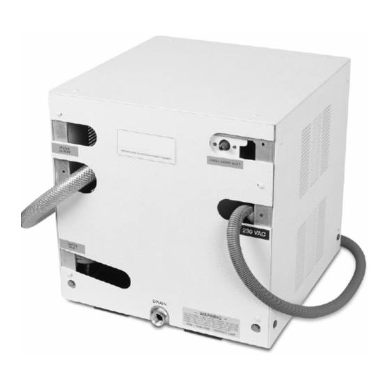
DIAGRAMS Eskimo Ice Installation & Operation Manual Figure 13: Diagram of System Components and Water Flow Figure 14: EI540D Connection Locations Seawater Out Fresh Water In Electrical Box Wire Ice Outlet Seawater In Drain L-3040 ENGLISH... -
Page 27: Electrical Wiring For 115V 60 H
DIAGRAMS Eskimo Ice Installation & Operation Manual 115V 60 H LECTRICAL IRING ODELS Figure 15: Wiring Diagram for 115V 60Hz Models L-3040 ENGLISH... -
Page 28: Electrical Wiring For 230V 60 H
DIAGRAMS Eskimo Ice Installation & Operation Manual 230V 60 H & 220V 50 H LECTRICAL IRING ODELS ODELS Figure 16: Wiring Diagram for 230V 60Hz Models and 220V 50 Hz Models L-3040 ENGLISH... - Page 30 Mobile living made easy. dometic.com YOUR LOCAL YOUR LOCAL YOUR LOCAL DEALER SUPPORT SALES OFFICE dometic.com/dealer dometic.com/contact dometic.com/sales-offi ces...
Need help?
Do you have a question about the Eskimo Ice EI540D and is the answer not in the manual?
Questions and answers