GEZE SecuLogic TZ 320 Installation, Wiring And Operation Instructions
Emergency exit system
Hide thumbs
Also See for SecuLogic TZ 320:

Related Manuals for GEZE SecuLogic TZ 320


Summary of Contents for GEZE SecuLogic TZ 320
- Page 1 GEZE SecuLogic EN Installation Wiring diagram Commissioning Emergency exit system Operation TZ 320 TZ 321 TZ 322 132916-03...
-
Page 2: Table Of Contents
Door control unit TZ 320 .....................................7 Classification in accordance with DIN EN 13637: 2015 ........................7 3.2.1 GEZE SecuLogic with TZ 320 and FTV 320 or MA 500 ........................7 3.2.2 GEZE SecuLogic with TZ 320 and FTÖ 332 ............................7 Door control unit TZ 321 .....................................8 Door control unit TZ 322 .....................................8... - Page 3 GEZE SecuLogic emergency exit system 5.4.5 Emergency exit sign (FWS)..................................16 5.4.6 Key switch SCT 320 ..................................... 16 5.4.7 Control door terminal TAN 320 ................................16 5.4.7.1 Terminal assignment TAN 320 .....................................16 Terminal box KL 220 ....................................17 5.5.1 Power supply .........................................17 5.5.2...
- Page 4 7.10.1 GEZE bus terminating resistor ................................52 7.10.1.1 Door control unit TZ 32x .......................................52 7.10.1.2 Master panel MTA 220 (panel TE 220) ................................52 7.10.2 GEZE bus ........................................52 7.10.3 Emergency unlocking via GEZE bus ..............................52 Commissioning ..............................53 Service mode ....................................... 53 8.1.1 Switching service mode on ..................................
-
Page 5: Introduction
GEZE SecuLogic emergency exit system Introduction 1. 1 Symbols and illustrations Warning notices In these instructions, warning notices are used to warn against material damage and injuries. Always read and observe these warning notices. Observe all measures marked with the warning symbol and warning word. -
Page 6: Basic Safety Notes
Safety notes à Only specialists who are authorised by GEZE are permitted to carry out installation, commissioning and maintenance. à If unauthorised changes are made to the system, GEZE cannot be made liable in any way whatsoever for any resulting damages. -
Page 7: Disposal
0/A/B EN 13637 GEZE SecuLogic comprising TZ 320 with FTV 320 or MA 500 is an electrically controlled emergency exit system, à that has been tested with 200 000 cycles, à for door leaves with a weight of up to 200 kg and a closing force of no more than 25 N à... -
Page 8: Door Control Unit Tz 321
EltVTR The GEZE SecuLogic emergency exit system - TZ 321 - with delayed emergency button - does not comply with the requirements of EltVTR or DIN EN 13637: 2015. Use of the TZ 321 in Germany must be applied for by agree-... -
Page 9: Abbreviations
GEZE SecuLogic emergency exit system Abbreviations 4. 1 Colours Colour Description Colour Description brown pink black blue turquoise green violet grey white orange yellow Abbreviations Abbreviation Description Alternating current Surface-mounted installation Fire alarm system GEZE bus (Controller Area Network) Direct current... -
Page 10: Technical Data
Variants TZ 320 Door control unit with GEZE bus TZ 321 Door control unit with GEZE bus and delayed emergency button TZ 322 Door control unit with GEZE bus without emergency push button Index B with illuminated emergency exit sign... -
Page 11: Components
Ribbon cable to SCT 320 or FWS 320 B Emergency push button illuminated (not with TST 322) X2 SCT external Infrared interface for ST 220 GEZE bus, supply, T 320, KL 220 Sabotage contact Reset switch indirect disconnection Buzzer (75 dB at 50 cm) -
Page 12: Ribbon Cable
GEZE SecuLogic emergency exit system 5.2.5 Ribbon cable Ribbon cable, mat. no. 131823 5.2.5.1 Assignment ribbon cable Terminal panel Terminal Function FWS 320 B – X1 SCT 320 – X2, X3 SCT 320 (unlock, acknowledge alarm) TST 32x – X1... -
Page 13: Door Controller Tst 32X
Door controller TST 320, door controller with GEZE bus, mat. no. 128958 Door controller TST 321, door controller with GEZE bus and delayed emergency button, mat. no. 128960 Door controller TST 322, door controller with GEZE bus, without emergency push button, mat. no. 128959 5.2.8.2 Terminal assignment... -
Page 14: Emergency Push Button Not 320
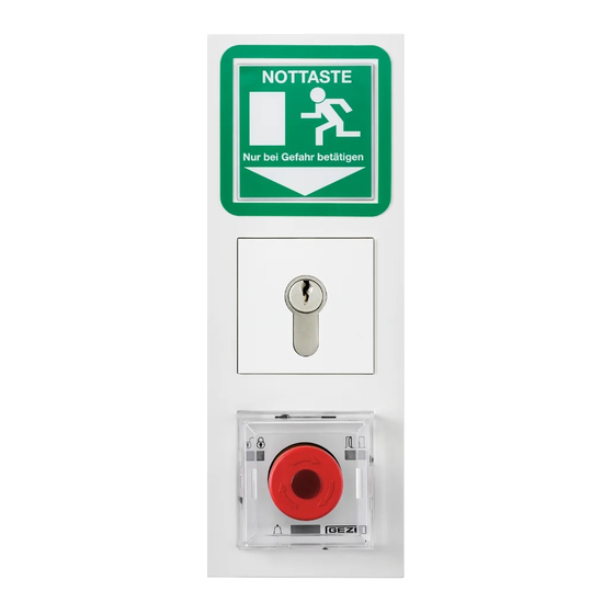
GEZE SecuLogic emergency exit system Emergency push button NOT 320 5.3. 1 Power supply Power supply 24 V DC, ±10% 5.3.2 Installation UP variant in UP box: Diameter 60 mm, depth 62 mm AP variant in AP-housing: 80 mm x 80 mm x 64 mm (W x H x D) 5.3.3... -
Page 15: Components
GEZE SecuLogic emergency exit system 5.4.3 Components FWS 320 B Ribbon cable to SCT 320 or TAN 320 SCT 320 Key switch 2 12 11 54 Ribbon cable to FWS 320 B Ribbon cable to TST 320 TAN 320 7 8 41 42 LED –... -
Page 16: Ribbon Cable
GEZE SecuLogic emergency exit system 5.4.4 Ribbon cable see chap. 5.2.5 5.4.5 Emergency exit sign (FWS) see chap. 5.2.6 5.4.6 Key switch SCT 320 see chap. 5.2.7 5.4.7 Control door terminal TAN 320 Control door terminal TAN 320, mat. no. 141033 5.4.7.1 Terminal assignment TAN 320... -
Page 17: Terminal Box Kl 220
GEZE SecuLogic emergency exit system Terminal box KL 220 EltVTR Terminal box KL 220 offers 4 additional inputs and 6 additional outputs. EN 13637 5.5. 1 Power supply Mains connection Fixed connection (installation cable) Power supply 230 V AC ±10%, 50 Hz Power supply NT19.2-24, 800 mA... - Page 18 GEZE SecuLogic emergency exit system Plug-in and screw terminals, max. cable cross-section: 1 mm² Terminal panel Terminal Function 24VDC (supply) RS485-B RS485-A max. 1 A, 30 VDC max. 1 A, 30 VDC max. 1 A, 30 VDC max. 1 A, 30 VDC max.
-
Page 19: Installation Of Door Control Unit Tz 32X And Door Terminal T 320
EN 13637 Distance to the main closing edge of the door less than 600 mm For this reason, GEZE recommends this position for the emergency push button to comply with the requirements from EltVTR and DIN EN 13637:2015: 90° 90°... -
Page 20: Installation Up Door Control Unit And Up Door Terminal
GEZE SecuLogic emergency exit system Installation UP door control unit and UP door terminal Installation is described using the example of TZ 320 BSN, EltVTR: FWS 320 B UP frame UP power supply Terminals Ribbon cable TST 320 SCT 320 Use UP boxes with a depth of 62.5 mm. - Page 21 GEZE SecuLogic emergency exit system Route mains connection cable, cables to the external assemblies and ribbon cable in the UP boxes Connect external assemblies to the terminals in accordance with the wiring diagram, see section 7. Connect the power supply in accordance with the wiring diagram (see 7.1.2) and insert behind the emergency exit sign in such a way that the 24 V side (RD, BK) is facing the emergency exit sign.
- Page 22 GEZE SecuLogic emergency exit system Mount assemblies and UP frame or stainless steel front plate. EltVTR Glue the adhesive frame (1) provided in place.
-
Page 23: Fasten The Impact Cover To The Support Ring
GEZE SecuLogic emergency exit system 6.3. 1 Fasten the impact cover to the support ring If necessary, the impact cover can be screwed to the support ring: Remove the inner part of the impact cover. To do this, press the inner part together at the two notches (1) and pull it out (2). -
Page 24: Installation Ap Door Control Unit And Ap Door Terminal
GEZE SecuLogic emergency exit system Installation AP door control unit and AP door terminal Installation is described using the example of TZ 320 BSN, EltVTR: 1 Door control unit TZ 320 BSN 2 Terminals Open housing. - Page 25 GEZE SecuLogic emergency exit system Mount wall bracket. For position of the emergency push button, see 6.1 Remove the mains connection cover. Connect the mains cable to the luster terminals in accordance with the wiring diagram, see 7.1.3 Mount the cover.
-
Page 26: Installation Of The Door Control Unit In The Stainless Steel Up Or Ap Box
GEZE SecuLogic emergency exit system 6.4. 1 Installation of the door control unit in the stainless steel UP or AP box. Installation of the door control unit is described using the example of TZ 320 BSN, EltVTR. Mount UP or AP box. - Page 27 GEZE SecuLogic emergency exit system Line-feed from the rear or from below possible. Route the mains connection cable / cables to the external assemblies in separate holes through the cable bushings. Insert the mains cable approx. 350 mm into the housing with sheath.
- Page 28 GEZE SecuLogic emergency exit system Plug terminals onto the TST 320. Fasten assemblies on the housing. Mount the front plate. Plug impact cover to TST 320. EltVTR Glue the adhesive frame (1) provided in place...
-
Page 29: Wiring Diagram
The automatic cut-out must have at least 4 A and may have maximum 16 A. 7. 1 . 1 Power supplies The GEZE SecuLogic emergency exit system uses these power supplies: Type max. current EltVTR NET 320, mat. -
Page 30: Mains Connection Of The Tz 32X Up Variants
GEZE SecuLogic emergency exit system 7. 1 .2 Mains connection of the TZ 32x UP variants The TZ 32x UP variants are protection class II devices, no protective earth conductor is connected. Miniature circuit breaker TZ 32x Lamp-wire connector Power supply... -
Page 31: Installation Of The Mains Connection Terminal And Mains Connection
GEZE SecuLogic emergency exit system 7.1.4.1 Installation of the mains connection terminal and mains connection Insert strain relief plate Connect earthing cable Connect the primary side Fit a split washer over the into the mains connec- to the mains connection of the power supply to M4 bolt for earthing. -
Page 32: Uninterruptible Power Supply Step Ups
GEZE SecuLogic emergency exit system 7. 1 .5 Uninterruptible power supply STEP UPS Uninterruptible power supply STEP UPS; 24 V, max. 3A, 46 Wh, mat. no. 193212 Power supply NT6.25A-24 HS, mat. no. 192113 Heed the instructions on the supplementary sheet for the uninterruptible power supply STEP UPS. -
Page 33: Holding Magnet Ma 500
GEZE SecuLogic emergency exit system 7.2.2 Holding magnet MA 500 Heed the supplementary sheet for the hold-open magnet MA 500 Reed switch contact set, mat. no. 106133 TST 32x MA 500 closed locked Locking device - Locking device + Door contact... -
Page 34: Operation Without Locking Mechanism
GEZE SecuLogic emergency exit system If several emergency exit electric strikes are connected, connect the locked messages in series using the relay board RP 220. FTÖ 332-2 FTÖ 332-1 TST 32x RP 220 COM1 closed locked Locking device - COM2 Locking device + 7.2.4... -
Page 35: External / Central Emergency Push Button
GEZE SecuLogic emergency exit system External / central emergency push button With indirect disconnection à one or more external emergency buttons which release the locking mechanism safely when actuated can be switched in the safety circuit of a door control unit, à... -
Page 36: Emergency Push Button Not 320
GEZE SecuLogic emergency exit system 7.3.1.2 Emergency push button NOT 320 Emergency push button NOT 320 see 5.3 Heed the supplementary sheet for the emergency push button NOT 320. NOT 320 TST 32x NOT 320 COM1 COM1 indirect disconnection NOT 320 indirect disconnection NC1 2kΩ... -
Page 37: Central Emergency Push Button
GEZE SecuLogic emergency exit system 7.3.2 Central emergency push button The supply of the safety circuit from the power supply of the first door control unit is shown. The current con- sumption of every door control unit in the safety circuit must heeded (see 7.1.1). If necessary, supply the safety circuit through a separate power supply. -
Page 38: Emergency Push Button Not 320
GEZE SecuLogic emergency exit system 7.3.2.2 Emergency push button NOT 320 Emergency push button NOT 320 see. 5.3. Heed the supplementary sheet for the emergency push button NOT 320. NOT 320 24VDC NOT 320 TST 32x-1 COM1 COM1 indirect disconnection... -
Page 39: Emergency-Off Panel In The Door Panel Te 220
GEZE SecuLogic emergency exit system 7.3.2.3 Emergency-off panel in the door panel TE 220 EltVTR Heed the supplementary sheet for the door panel TE 220. EN 13637 MTA 220 TST 32x-1 Emergency push indirect disconnection button Emergency push indirect disconnection... -
Page 40: Key Switch Sct 222
GEZE SecuLogic emergency exit system 7.4.2 Key switch SCT 222 One-pole reversible push button (two normally open contacts) with LEDs Relay board RP 220, mat. no. 102355 Heed the supplementary sheet for the key switch SCT 222. The green/red LED indicates the state at the locked input of the door controller. Relay board RP 220 is required for this. -
Page 41: Key Switch Sct 320
GEZE SecuLogic emergency exit system 7.4.3 Key switch SCT 320 One-pole reversible push button (two normally open contacts) with sabotage contact key switch SCT 320 see 5.2.7 SCT 320 TST 32x 24V 2 lock, short-time unlocking, lock acknowledge unlock, acknowledge... -
Page 42: Motor Lock Iq Lock El With Mst 210
GEZE SecuLogic emergency exit system TST 32x IQ lock EM Door handle contact (NO) GY/PK Cylinder RD/BU contact (NO) Magnet - Magnet + closed locked Locking device - Locking device + TST 32x If the IQ lock EM is to be engaged for the duration of unlocking: Output PA1 to BA. -
Page 43: Automatic Swing Door Drive
à Set the parameter for output PA2 to BA. drive and the type of contact to Normally open contact. Parameter settings of the control unit of the swing door drive (only possible with ST 220 or GEZE connects): à Set the parameter for the type of contact at input NA to Normally closed contact. - Page 44 GEZE SecuLogic emergency exit system When the door control unit is unlocked, the swing door drive changes to mode of operation AU due to a short pulse and switches the lock to daytime operation. The swing door drive opens via the contact sensor connected.
-
Page 45: Swing Door Drive Emd
GEZE SecuLogic emergency exit system 7.6.2 Swing door drive EMD Heed the wiring diagram for the swing door drive EMD. 7.6.2.1 Operating EMD via internal programme switch à Set the parameter for output PA1 to Activ. drive and the type of contact to normally open contact. -
Page 46: Configurable Inputs
GEZE SecuLogic emergency exit system The mode of operation of the drive can be changed at the DPS, TPS or MPS. When the door control unit is locked, the swing door drive changes to mode of operation NA. Short-time unlocking at the door control unit activates the swing door drive via its input KB. The drive opens the door. -
Page 47: Sabotage
GEZE SecuLogic emergency exit system 7.7. 1 Sabotage The example shows the connection of a key switch SCT 320 (sabotage contact) to the door controller. Set the parameter for input PE1 of the door controller to Sabotage ext. and the type of level to Low active. -
Page 48: Key Switch Sct 221
GEZE SecuLogic emergency exit system 7.7.2.2 Key switch SCT 221 One-pole push button (normally open contact) Heed the supplementary sheet for the key switch SCT 221 TST 32x SCT 221 closed locked Locking device - Locking device + 7.7.2.3 Number code lock TOPLOCK CTI, CTI B EltVTR Heed the supplementary sheet for the number code lock TOPLOCK CTI resp. -
Page 49: Number Code Lock Toplock Cts V, Cts Bv
GEZE SecuLogic emergency exit system 7.7.2.4 Number code lock TOPLOCK CTS V, CTS BV EltVTR Heed the supplementary sheet for the number code lock TOPLOCK CTS V resp. TOPLOCK CTS BV! EN 13637 DANGER Danger of fatal injury due to electric shock! Ensure that the connection to the mains voltage is carried out by a qualified electrician. -
Page 50: Configurable Outputs
GEZE SecuLogic emergency exit system Configurable outputs The door control unit TZ 32x has two configurable outputs through which different functions can be realised (see 8.1.5). Not all the possible functions are shown here. The function and type of contact of the configurable outputs is set in the service menu. -
Page 51: Geze Bus
Several door control units TZ 32x and panels TE 220 communication via the GEZE bus. A maximum of 63 devices can be connected to the GEZE bus, a maximum of 5 of these may be panels TE 220. Each device must have an unambiguous address. The address is set in the service menu of the door control unit TZ 32x or the master panel MTA 220 - parameter Bus address. -
Page 52: Geze Bus Terminating Resistor
GEZE bus when the emergency push button is pressed. Every door control unit can be configured at the GEZE bus as to whether the door control unit responds to the emergency unlocking and unlocks (service menu, parameter Emergency unlocking). -
Page 53: Commissioning
GEZE SecuLogic emergency exit system Commissioning 8. 1 Service mode In service mode, the parameters for the door control unit can be set using service terminal ST 220 and a diagno- sis can be carried out. 8. 1 . 1 Switching service mode on It is only possible to switch service mode on when neither an alarm nor emergency unlocking is queued. -
Page 54: Connecting Service Terminal St 220 To The Door Control Unit
GEZE SecuLogic emergency exit system 8. 1 .3 Connecting service terminal ST 220 to the door control unit Heed the supplementary sheet for the service terminal ST 220 The service terminal is connected to the door control unit via an infrared interface. -
Page 55: Service Menu St 220
GEZE SecuLogic emergency exit system 8. 1 .5 Service menu ST 220 The door control unit is configured via the service menu of the ST 220 and the memory with alarms and error messages can be read out. To do this, change the door control unit to service mode and connect the service terminal to the door control unit. - Page 56 GEZE SecuLogic emergency exit system 2nd level 3rd level 4th level 5th level 6th level Selection Comments (factory setting) Param. Control unit Configuration Selection Sabotage ext. Sabotage alarm and message - level inputs input 1 Unlock System goes into unlocked state - flank...
- Page 57 GEZE SecuLogic emergency exit system 2nd level 3rd level 4th level 5th level 6th level Selection Comments (factory setting) Activ. direct Contact closes when the emergency push but- ton is pressed on the TZ 320. Activ. indirect Contact closes with indirect disconnection.
- Page 58 Selection Terminal box Selection Door terminal Selection Automatic Selection If a GEZE swing door drive Invers is connected, yes must be configured. Activation of the Invers emergency exit electric strike is through the swing door drive. Timer Timer 1 Time start...
- Page 59 GEZE SecuLogic emergency exit system 2nd level 3rd level 4th level 5th level 6th level Selection Comments (factory setting) Time end End hours Change value Time at which the timer becomes Inactive End minutes Change value … Days Monday Selection...
- Page 60 GEZE SecuLogic emergency exit system 2nd level 3rd level 4th level 5th level 6th level Selection Comments (factory setting) Bus address Change value 0 No connections to the bus A bus address may only occur once on a bus line. Bus addresses already assigned are skipped in the service menu.
- Page 61 GEZE SecuLogic emergency exit system 2nd level 3rd level 4th level 5th level 6th level Selection Comments (factory setting) active In the basic state, all the doors are locked and closed. Only one door at a time in the security interlocking door group can be unlocked short- term.
- Page 62 GEZE SecuLogic emergency exit system 2nd level 3rd level 4th level 5th level 6th level Selection Comments (factory setting) Alarm memory Display list Alarm and error messages are saved in the alarm memory of the door control unit and can be read out using the service terminal. The service terminal shows the last 20 alarm and error messages with date, time and reason.
-
Page 63: Display Of Alarms And Faults
NT TT pressed Indirect disconnection through door terminal Reset emergency push button on the door terminal Fuse defective Fuse F1 is defective Replace fuse (GEZE ID no. 138362) Dir. disconnection NT TZ pressed Direct disconnection through internal Reset emergency push button on door control unit... -
Page 64: Operation
GEZE SecuLogic emergency exit system Operation Emergency exit sign Key switch Control unit with emergency push button 9. 1 Signals 9. 1 . 1 Alarm signals No. Display Colour Meaning Locked Red flashing (every second) Interlocking door system occupied Red flashing (every 2 seconds) -
Page 65: Controlling The Door Control Unit Via Key Switch
GEZE SecuLogic emergency exit system Alarm Signal horn Pre-alarm 2 beeps Alarm 4 seconds permanent tone -Door alarm -Emergency push button pressed -Emergency unlocking via BMA, RWA Alarm time Sabotage alarm 4 beeps Alarm time Controlling the door control unit via key switch Control of the door control unit is possible using the integrated or an external key switch, if available. -
Page 66: Locking The Door
GEZE SecuLogic emergency exit system 9.2.2 Locking the door The door is unlocked and closed, otherwise short-time unlocking or pre-alarm is triggered. Turn the key to the right. LEDs 1 and 2 light up red. The door is locked. Through the locking mechanism, an interlocking function switched off at the door is switched on. -
Page 67: Resetting Alarm
Acknowledge the alarm via the key switch (see 9.4.5). 9.4.3 Resetting emergency unlocking Emergency unlocking is the unlocking of the door by a BMA or RWA or via the GEZE bus. Reset the cause of emergency unlocking. Acknowledge alarm via: à... -
Page 68: Acknowledging Alarm With Key Switch
If the power supply is not buffered via an uninterruptible power supply, the door is not monitored and can be passed through in the event of a power failure. The GEZE SecuLogic emergency exit system saves the mode of operation currently set so that this is active again after the power supply has been restored:... - Page 69 GEZE SecuLogic emergency exit system...
- Page 70 GEZE SecuLogic emergency exit system...
- Page 71 GEZE SecuLogic emergency exit system...
- Page 72 97944 Boxberg-Schweigern Tel. +49 (0) 7930 9294 0 Baltic States Iberia Singapore Fax +49 (0) 7930 9294 10 GEZE GmbH Baltic States office GEZE Iberia S.R.L. GEZE (Asia Pacific) Pte, Ltd. E-Mail: sk.de@geze.com E-Mail: office-latvia@geze.com E-Mail: info@geze.es E-Mail: gezesea@geze.com.sg www.geze.com...
Need help?
Do you have a question about the SecuLogic TZ 320 and is the answer not in the manual?
Questions and answers