Table of Contents
Advertisement
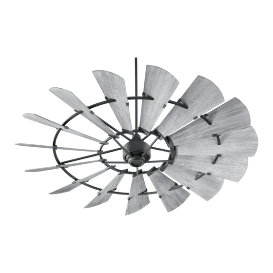
THE WINDMILL CEILING FAN
INSTALLATION INSTRUCTIONS
Please read and save these instructions
These instructions are to be used in
the installation of the following
QUORUM INTERNATIONAL fans...
The Windmill
(w/ optional light feature)
© 2018 Quorum International. All Rights Reserved.
P.O. Box 961008 • Fort Worth, TX 76161 • (817) 626-5483 • FAX (817) 626-5540
I0272-12/18
Advertisement
Table of Contents

Subscribe to Our Youtube Channel
Related Manuals for Quorum Windmill 96015 Series


Summary of Contents for Quorum Windmill 96015 Series
- Page 1 These instructions are to be used in the installation of the following QUORUM INTERNATIONAL fans... The Windmill (w/ optional light feature) © 2018 Quorum International. All Rights Reserved. P.O. Box 961008 • Fort Worth, TX 76161 • (817) 626-5483 • FAX (817) 626-5540 I0272-12/18...
-
Page 2: Warranty & Service
Complete and mail the enclosed (RGA) prior to returning the defective box and packaging. Quorum will not bear warranty card within 10 days to ensure unit or part. Call (817) 626-5483 - responsibility for any shipping damage. -
Page 3: Safety Rules
Screw No. 4: Blade arm screws with lock washers (1/4"x38mm) (6 pcs) Screw No. 5: Blade arm screws with lock washers (3/16"x15mm) (11 pcs) IF YOU FIND THAT PARTS ARE MISSING. CONTACT YOUR DEALER FOR REPLACEMENT, OR CALL QUORUM DIRECTLY AND WE WILL MAIL REPLACEMENTS TO YOU IMMEDIATELY. -
Page 4: Mounting Options
3. MOUNTING OPTIONS 1. Disconnect the power by removing fuses or turning off circuit breakers. Fig. 1 Ceiling Joists 2. The support structure must be securely mounted and capable of reliably supporting a minimum of 50 pounds (22.7 kg). WARNING: Support Directly from the Building Structure. 3. -
Page 5: Hanging Your Fan
4. HANGING YOUR FAN WARNING -Turn off the power! WARNING - To avoid damage to fan Fig. 6 Fig. 4 parts (especially the downrod yoke), DO NOT use pneumatic or electric drivers Downrod exceeding to 23 KGS of torque. assembly Outlet box 1. -
Page 6: Attaching The Fan Blades
5. ATTACHING THE FAN BLADES WARNING -Turn off the power! NOTE: Please see the label of the blade Fig. 8 Fig. 10 side up as illustration shown for assembly. Blade deco bar Fan blade screws (Screw No. 2) 1. Slide the blade deco plate to position Blade deco bar Hole the blade hole on the center of the blade. - Page 7 6. ATTACHING THE BLADE ARMS WARNING -Turn off the power! Fig. 12 1. Carefully lift the blade circle to the fan assembly. (Fig. 12) Important assembly process, it is a must to require 3 persons at least to lift the blade circle evenly onto the fan body and positioning the blade holes at inner circle.
-
Page 8: Electrical Connections
Secure the transmitter with the two screws provided. Attach the face plate over the transmitter with the two screws provided. Use ONLY remote controls approved by Quorum. Use of unapproved remote controls will cause unacceptable humming noise, and avoids the fan warranty. - Page 9 8. COMPLETING INSTALLATION 1. Make sure the wiring is safely inside the Fig. 19 Fig. 18 outlet box as instructed in Step 5 - Electrical Connections. To install the Outlet box canopy, slide the canopy up to hanger bracket and place the key hole on the canopy over the screw on the hanger Hanger bracket...
- Page 10 10. OPERATING TRANSMITTER YOUR Your DC brushless motor is equipped with Pairing Process Fig. 21 With the fan’s power off, restore power to an automatically learned type remote the fan. Press and hold “ ” button for control. There is no frequency switches on about 5 seconds and release.
- Page 11 11. FAN OPERATION AND CARE 1. A ceiling fan is an environmentally 3. Clean you fan periodically using only Fig. 23 smart choice to cool as well as to help a cloth dampened with a mild detergent warm your home or office. Adjust your solution for all hardware - never use HVAC thermostat during fan use to save solvents.
-
Page 12: Troubleshooting
12. TROUBLESHOOTING FAN WILL NOT START 3. Use of a standard light rheostat or an EXCESSIVE WOBBLE 1. Check that the electricity has been unapproved fan remote control to control Note: A small amount of wobble is turned on at the circuit breaker which had the fan speed will always cause an considered acceptable and should not be probably been turned off during...
Need help?
Do you have a question about the Windmill 96015 Series and is the answer not in the manual?
Questions and answers