Advertisement
Quick Links
Build Your Own Clone
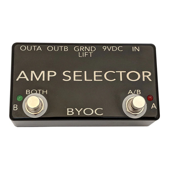
Amp Selector and Stereo FX Router
Kit Instructions
Warranty:
BYOC, LLC guarantees that your kit will be complete and that all parts and components
will arrive as described, functioning and free of defect. Soldering, clipping, cutting,
stripping, or using any of the components in any way voids this guarantee. BYOC, LLC
guarantees that the instructions for your kit will be free of any majors errors that would
cause you to permanently damage any components in your kit, but does not guarantee
that the instructions will be free of typos or minor errors. BYOC, LLC does not
warranty the completed pedal as a whole functioning unit nor do we warranty any of the
individual parts once they have been used. If you have a component that is used, but
feel it was defective prior to you using it, we reserve the right to determine whether or
not the component was faulty upon arrival. Please direct all warranty issues to:
sales@buildyourownclone.com This would include any missing parts issues.
Return:
BYOC, LLC accepts returns and exchanges on all products for any reason, as long as
they are unused. We do not accept partial kit returns. Returns and exchanges are for the
full purchase price less the cost of shipping and/or any promotional pricing. Return
Advertisement

Related Manuals for BYOC Amp Selector and Stereo FX Router


Summary of Contents for BYOC Amp Selector and Stereo FX Router
- Page 1 Kit Instructions Warranty: BYOC, LLC guarantees that your kit will be complete and that all parts and components will arrive as described, functioning and free of defect. Soldering, clipping, cutting, stripping, or using any of the components in any way voids this guarantee. BYOC, LLC...
-
Page 2: Tech Support
That being said, we will do our best to help you as much as we can. Our philosophy at BYOC is that we will help you only as much as you are willing to help yourself. We have a wonderful and friendly DIY discussion forum with an entire section devoted to the technical support and modifications of BYOC kits. - Page 3 AMP SELECTOR & STEREO FX ROUTER KIT INSTRUCTION INDEX Parts Checklist ....page 4 - 5 Populating the Circuit Board ....page 6 - 13 Main PCB Assembly .........page 14 - 17 Wiring................page 18 - 21 Operation Overview..........page 22 Schematic..............page 23 - 24...
- Page 4 1 - MAX1044 4 - DIP8 IC sockets Hardware: 1 - drilled enclosure w/ 4 screws 1 - byoc classic Amp selector PCB 2 - 3PDT footswitches 2 - SPDT Toggle switches 1 - PC mount DC adapter jack 4 - ¼ PC mount stereo jack...
- Page 5 Step 1: Populate the circuit board Step 1a: Add the Resistors. Resistors are not polarized and can be inserted into the circuit board in either direction.
- Page 6 Step 1b: Add the diode. The diode will have a white or gray strip on one end. Match this strip up with the picture on the circuit board. Step 1c: Add the IC sockets. DO NOT ADD THE ACTUAL IC's YET!!!! Only add the sockets.
- Page 7 Step 1d: Add the film capacitors. These are not polarized and can go into the pcb in either direction. Step 1e: Add the electtrolytic capacitors. These are polarized. The positive lead will be the longer lead and will go into the square solder pad. The negative lead will be the shorter lead and will go into the round solder pad.
- Page 8 Step 1f: Add the transformers. The primary side of the transformer will be marked with a . Orient the transformer so that the side with the P matches up with the side of the pcb marked with a P. Note that there are two tabs on each transformer. You should not solder these tabs to the pcb.
- Page 9 Step 2: Very loosely install the 1/4 jacks in the enclosure with the solder pins facing up. You do not want to tighten the nuts very much because you want to be able to adjust the fit of the PCB before you solder it to the jacks. Step 3: DO NOT SOLDER ANYTHING YET!!!! Install the populated PCB so that it fits onto the jacks.
- Page 10 PCB is well centered inside the enclosure. You also want to make sure that the eyelet for the DC adapter jact is in line with the center of the DC adapter jack hole. It would be a good idea to put the DC adapter jack into the PCB without soldering it just to test the fit.
- Page 11 Step 5: Put the PCB/Jack assembly back into the PCB. Tighten the jack nuts with just your fingers. You do not need to make them very tight yet. You do not need to put the toggle switches into their respective holes at this point because you will be removing the assembly again, but you can if you'd like.
- Page 12 Step 5a: Install the footswitches. Orient the footswitches so that the flat sides of the solder lugs are like the diagram below. NOTE: There are no actual number markings on the footswitches. There are two correct ways you can orient the footswitches. They are both 180 degrees of each other.
- Page 13 Step 5b: Connect the footswitches to the PCB. Connect each solder lug of each footswitch to its respective numbered solder pad on the PCB.
- Page 14 Step 6a: Install the DC adpater jack into the PCB, but DO NOT SOLDER YET!!!! Step 6b: Before you solder the DC adapter jack, check again to make sure that it is properly lined up with the DC adapter jack hole in the enclosure. If it is not, there is a small amount of play between the DC adapter jack and it's space on the PCB for you to adjust the fit.
- Page 15 Step 6c: Make sure the DC adapter jack stays in place and solder just the +battery solder pad on the top side of the PCB. Remove the PCB assembly from the enclosure again and solder the other two terminals of the DC adapter jack to the PCB on the bottom side of the PCB.
- Page 16 Step 7a: Install the LEDs into the PCB assembly, but do not solder them yet. Be sure to insert them into the bottom side of the PCB. The longer lead of the LED goes into the square solder pad. The shorter lead goes into the round pad. It doesn't matter which color LED goes on which side.
- Page 17 Step 7b: Install the PCB assembly back into the enclosure. Make sure the DC adapter jack is lined up, and tighten the jack nuts with your fingers (yes, this will be the last time you have to install the PCB assembly). Using the excess LED leads as handles, adjust the LEDs so that they fit into their holes as shown in the picture above.
- Page 18 Step 7c: Flip the entire unit over and solder the LEDs. Clip the excess leads off at the circuit board. Step 8: Install the IC's into their sockets. Be absolutely certain to orient the IC's correctly. Read the next page for IC orienting instructions.
- Page 19 That's it! You're done!
-
Page 20: Operating Overview
Operating Overview Power Supply: Standard Guitar FX power supply (9VDC 2.1mm or 2.1mm negative tip) Current Draw: 12mA A/B footswitch: Selects between OUT A and OUT B BOTH footswitch: Turns both OUT A and OUT B on at the same time. IN A (with no plug in IN B): Sends signal to both OUT A and OUT B. - Page 22 Please visit http://buildyourownclone.com/board for any technical support http://buildyourownclone.com/ampselectorschematic.pdf to download high res schematic. copyright 2011 B.Y.O.C., Inc.
Need help?
Do you have a question about the Amp Selector and Stereo FX Router and is the answer not in the manual?
Questions and answers