Advertisement
Quick Links
Build Your Own Clone
Amp Selector and Stereo FX Router
Kit Instructions
Warranty:
BYOC, Inc. guarantees that your kit will be complete and that all parts and
components will arrive as described, functioning and free of defect. Soldering,
clipping, cutting, stripping, or using any of the components in any way voids this
guarantee. BYOC, Inc. guarantees that the instructions for your kit will be free of
any major errors that would cause you to permanently damage any components in
your kit, but does not guarantee that the instructions will be free of typos or minor
errors. BYOC, Inc. does not warranty the completed pedal as a whole functioning
unit, nor do we warranty any of the individual parts once they have been used. If
you have a component that is used, but feel it was defective prior to you using it, we
reserve the right to determine whether or not the component was faulty upon
arrival. Please direct all warranty issues to:
sales@buildyourownclone.com This would include any missing parts issues.
Return:
BYOC, Inc. accepts returns and exchanges on all products for any reason, as long as they
are unused. We do not accept partial kit returns. Returns and exchanges are for the full
purchase price less the cost of shipping and/or any promotional pricing. Return shipping
is the customer's responsibility. This responsibility not only includes the cost of
shipping, but accountability of deliver as well. Please contact
sales@buildyourownclone.com to receive a return authorization before mailing.
1
Advertisement

Related Manuals for BYOC Amp Selector and Stereo FX Router


Summary of Contents for BYOC Amp Selector and Stereo FX Router
- Page 1 This would include any missing parts issues. Return: BYOC, Inc. accepts returns and exchanges on all products for any reason, as long as they are unused. We do not accept partial kit returns. Returns and exchanges are for the full purchase price less the cost of shipping and/or any promotional pricing.
- Page 2 That being said, we will do our best to help you as much as we can. Our philosophy at BYOC is that we will help you only as much as you are willing to help yourself. We have a wonderful and friendly DIY discussion forum with an entire section devoted to the technical support and modifications of BYOC kits.
- Page 3 AMP SELECTOR & STEREO FX ROUTER KIT INSTRUCTION INDEX Parts Checklist---------------------------------------------page 4 Assembly----------------------------------------------------page 6 - 18 Installing the ICs------------------------------------------page 19 Operation Overview--------------------------------------page 20 Schematic---------------------------------------------------page 21 PCB Map---------------------------------------------------page 22...
- Page 4 1 - 7660SCPA 3 - DIP8 IC sockets Hardware: 1 - Drilled enclosure w/ 4 screws (optional) 1 - BYOC Amp selector PCB 2 - 3PDT footswitches 1 - SPDT On-On Toggle switches 1 - DC Jack (optional 2 - LEDs (optional) 2 - Enclosed ¼”...
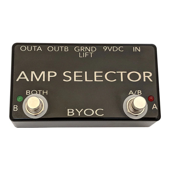
- Page 5 This is what your finished pedal should look like. Your kit may come with different color components, but they will still do the exact same thing.
- Page 6 Populating The Circuit Board Step 1: Add the Resistors. Resistors are not polarized and can be inserted into the circuit board in either direction.
- Page 7 Step 2: Add the diode. The diode will have a white or gray strip on one end. Match this strip up with the picture on the circuit board.
- Page 8 Step 3: Add the IC sockets. DO NOT ADD THE ACTUAL IC's. Only add the sockets. The sockets get solder to the circuit board. The IC's go in the sockets and do not get soldered. Make sure to match the side of the socket with the “U-Shaped” notch to the picture on the circuit board.
- Page 9 Step 4: Add the film capacitors. These are not polarized and can go into the PCB in either direction.
- Page 10 Step 5: Add the electrolytic capacitors. These are polarized. The positive lead will be the longer lead and will go into the square solder pad. The negative lead will be the shorter lead and will go into the round solder pad. The negative side of will usually also have a stripe running down the side of the capacitor body.
- Page 11 Step 6: Add the transformer. The primary side of the transformer will be marked with a “P”. Orient the transformer so that the side with the P matches up with the side of the PCB marked with a P. Note that there are two tabs on the transformer. You should not solder these tabs to the PCB.
- Page 12 Main PCB Assembly Step 1: Cut 11 pieces of 2.5 inch wire and solder them to the board. This will allow you to wire the hardware a bit easier later.
- Page 13 Step 2: Add the standoffs and LEDs to the board. The standoffs will snap into the holes, so push them until you hear them click. DO NOT SOLDER THE LED YET. You will solder them in the next step. Remove the paper backing of the standoffs to reveal the adhesive.
- Page 14 Step 3: Using the LEDs as your guides, place the PCB into the enclosure so that the bottom edge of the PCB is against the wall of the enclosure. If your LEDs are lined up, the rest of the board will be lined up too. At this point, apply a little pressure to the standoffs so they stick to the inside of the enclosure.
- Page 15 Step 4: Install the footswitches. Orient the footswitches so that the flat sides of the solder lugs are like the diagram below. NOTE: There are no actual number markings on the footswitches. There are two correct ways you can orient the footswitches. They are both 180 degrees of each other.
- Page 16 Step 4a: Wire the footswitches to the board. Connect the lug number to the eyelet number.
- Page 17 Step 5: Add the hardware. Be mindful of the orientation of the jacks. The green arrows are pointing to the SLEEVE side.
- Page 18 Step 6: Connect the wires to the respective hardware lugs.
- Page 19 That's it! You're done!
- Page 20 Operating Overview Power Supply: Standard Guitar FX power supply (9VDC 2.1mm or 2.1mm negative tip) Current Draw: 12mA A/B footswitch: Selects between OUT A and OUT B BOTH footswitch: Turns both OUT A and OUT B on at the same time. IN: Signal input.
- Page 22 PCB Map...
- Page 23 Please visit http://byocelectronics.com/board for any technical support http://byocelectronics.com/ampselectorschematic.pdf to download high res schematic. Copyright 2019 B.Y.O.C., Inc.
Need help?
Do you have a question about the Amp Selector and Stereo FX Router and is the answer not in the manual?
Questions and answers