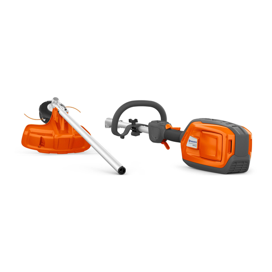
Husqvarna 325iLK Operator's Manual
Hide thumbs
Also See for 325iLK:
- Operator's manual (456 pages) ,
- Workshop manual (28 pages) ,
- Operator's manual (24 pages)
Advertisement
Advertisement
Table of Contents

Summary of Contents for Husqvarna 325iLK
- Page 1 325iLK Operator's manual 2-16...
-
Page 2: Table Of Contents
Contents Introduction..............2 Troubleshooting............13 Safety................3 Transportation, storage and disposal......13 Assembly................ 9 Technical data.............. 14 Operation..............10 Accessories..............15 Maintenance..............12 EC Declaration of Conformity........16 Introduction Intended use Accessories on page 15 . Make sure to accessories in read this manual together with the approved accessory This power unit is a bare unit that only function together manual. -
Page 3: Safety
Note: Other symbols/decals on the product refer to Maximum speed of the output shaft. /min certification requirements for other commercial areas. Manufacturer Rated voltage, V Husqvarna AB Drottninggatan 2, SE-561 82 Huskvarna, Sweden, tel: +46-36-146500 Direct current. Product liability The product agrees with the applicable EC As referred to in the product liability laws, we are not directives. - Page 4 Power tool use and care refrigerators. There is an increased risk of electric shock if your body is earthed or grounded. • Do not force the power tool. Use the correct power • Do not expose power tools to rain or wet conditions. tool for your application.
- Page 5 • Do not use a battery pack or tool that is damaged or • Check that the trimmer head and trimmer guard are modified. Damaged or modified batteries may exhibit not damaged or cracked. Replace the trimmer head unpredictable behaviour resulting in fire, explosion or or trimmer guard if it has been exposed to impact or risk of injury.
- Page 6 described in this manual. Some maintenance and attachment guard. Stones, rubbish, etc., can be service measures must be carried out by trained and thrown up into the eyes which can cause blindness qualified specialists. See instructions under the or serious injury. Maintenance heading.
- Page 7 ANSI Z87.1 standard in the USA or EN 166 in EU carried out correctly and if service and/or repairs are not countries. carried out professionally. If you need further information please contact your nearest servicing dealer. WARNING: Never use a product with defective safety components.
- Page 8 6. Release the power trigger and make sure that the cutting attachment stops and remains still. Safety instructions for assembly WARNING: Read this power unit manual together with approved accessory manual. • Remove the battery from the product before you assemble the product.
-
Page 9: Assembly
Assembly To assemble the loop handle 2. Align the tab (A) with the arrow (B) on the coupling. 1. Attach the loop handle onto the shaft between the arrows. Do not place loop handle or suspension ring on label. 3. Push the shaft into the coupling until it clicks into position. -
Page 10: Operation
WARNING: Read and understand the safety chapter before you use the product. To connect the battery to the product WARNING: Only use Husqvarna original batteries with the product. 1. Make sure that the battery is fully charged. CAUTION: If the battery does not move easily into the battery holder, the battery is not installed correctly. - Page 11 Work position 1. Push the mode button to set a limit to the maximum speed. The white LEDs comes on to show that the • Hold the product with 2 hands. function is on. • Hold the product on the right side of your body. •...
-
Page 12: Maintenance
Maintenance Introduction Maintenance schedule WARNING: Before you do any maintenance work you must read and understand the WARNING: Remove the battery before you do maintenance. safety chapter. The following is a list of the maintenance steps that you must do on the product. Maintenance Daily Weekly... -
Page 13: Troubleshooting
Troubleshooting Keypad LED display Possible faults Possible action Green activate LED flashing Low battery voltage. Charge the battery. Red error LED flashing Overload. The cutting attachment is jammed. deacti- vate the product. Remove the battery. Clean the cutting attachment from unwanted mate- rials. -
Page 14: Technical Data
Technical data Technical data 325iLK together with approved ac- cessories Motor Motor type BLDC (brushless) 36V Speed of output shaft, 1/min 8400 Weight Weight (power unit only), kg Noise emissions Sound power level, measured dB (A) 89-103 Sound power level, guaranteed L... -
Page 15: Accessories
Power, W Accessories Attachments Approved attachments Attach- Attach- Use with ment num- ment group Brush cutter attachment BCA850 1-10 325iLK Blower attachment BA101 11-20 325iLK Edger attachment ECA850 21-30 325iLK Edger attachment ESA850 21-30 325iLK Hedge trimmer attachment HA850 31-40... -
Page 16: Ec Declaration Of Conformity
EC Declaration of conformity Husqvarna AB, SE-561 82 Huskvarna, Sweden, tel: +46-36-146500, declares under sole responsibility that the battery Husqvarna 325iLK from 2019’s serial numbers and onwards (the year is clearly stated in plain text on the type plate with subsequent serial number),... - Page 17 1318 - 002 - 04.12.2019...
- Page 18 1318 - 002 - 04.12.2019...
- Page 19 1318 - 002 - 04.12.2019...
- Page 20 Original instructions 1142131-26 2019-12-06...


Need help?
Do you have a question about the 325iLK and is the answer not in the manual?
Questions and answers