Table of Contents
Advertisement
Quick Links
Advertisement
Table of Contents

Subscribe to Our Youtube Channel
Related Manuals for Dell EMC PowerStore Series


Summary of Contents for Dell EMC PowerStore Series
- Page 1 Dell EMC PowerStore Hardware Information Guide...
- Page 2 Notes, cautions, and warnings NOTE: A NOTE indicates important information that helps you make better use of your product. CAUTION: A CAUTION indicates either potential damage to hardware or loss of data and tells you how to avoid the problem. WARNING: A WARNING indicates a potential for property damage, personal injury, or death.
-
Page 3: Table Of Contents
Contents Additional Resources........................4 1 Platform overview........................5 Description....................................5 2 Base enclosure component descriptions..................6 Base enclosure component overview..........................6 Base enclosure front view..............................7 System identification tags.............................. 8 Base enclosure rear view..............................8 Base enclosure embedded modules and 4-port cards....................9 Base enclosure I/O module types.......................... -
Page 4: Additional Resources
Preface Additional Resources As part of an improvement effort, revisions of the software and hardware are periodically released. Some functions that are described in this document are not supported by all versions of the software or hardware currently in use. The product release notes provide the most up-to-date information about product features. -
Page 5: Platform Overview
Platform overview Description The PowerStore platform has a flexible design capable of meeting the requirements of multiple different storage applications with support for high availability. The design includes two major configurations: • PowerStore T model appliances • PowerStore X model appliances PowerStore T model appliances serve Block and File services, and the software stack is deployed directly on the system. -
Page 6: Base Enclosure Component Descriptions
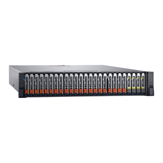
Base enclosure component descriptions Base enclosure component overview The 2U, 25-drive base enclosure consists of the following components: • Slots for 25 2.5-inch drives • Midplane • Node • Power supply module • EMI shielding Drives Each drive resides in a drive carrier. The drive carriers are metal and plastic assemblies that provide smooth, reliable contact with the enclosure slot guides and mid-plane connectors. -
Page 7: Base Enclosure Front View
EMI shielding EMI compliance requires a properly installed electromagnetic interference (EMI) shield in front of the base enclosure drives. When installed in cabinets that include a front door, the base enclosure includes a simple EMI shield. Other installations require a front bezel that has a locking latch and integrated EMI shield. -
Page 8: System Identification Tags
Location State Description Drive activity Blue Drive activity. Drive is powered off. Base enclosure power and fault Blue Power is on. No fault has occurred. Amber Power is on. Fault has occurred within the enclosure. Blue and amber alternating System not initialized. Power is off. -
Page 9: Base Enclosure Embedded Modules And 4-Port Cards
• Two optional I/O modules • One power supply module Figure 5. Base enclosure rear view with hardware component locations Table 3. Base enclosure hardware component locations Location Description Node B Node A Power supply module I/O module, slots 0 and 1 Embedded module Base enclosure embedded modules and 4-port cards About embedded modules... - Page 10 Figure 6. Embedded module rear view with component locations Table 4. Embedded module component locations Location Description 4-port card Mini serial port (unused) Mini-SAS HD back-end ports DB9 serial port (service) RJ-45 LAN connector - service port RJ 45 LAN connector - system management port. Only used on PowerStore T model. Not used on PowerStore X model.
-
Page 11: Base Enclosure I/O Module Types
Table 5. Embedded module LEDs Location State Description Embedded module power Amber Embedded module has faulted. No fault has occurred, normal operation. Ethernet port link Green Link established. No link established. Ethernet port activity Amber blinking Port activity. No port activity. SAS port/activity Link Blue SAS port link is up. -
Page 12: Port Labels In Powerstore Manager
4-port 32Gb Fibre Channel I/O module The 4-port 32Gb Fibre Channel I/O module is used to serve Fibre Channel block protocol via SAN to hosts for the platform. The I/O module is available with either 16G FC SFP modules or with 32G FC SFP modules. Each port has an optical 16G/32G capable SFP connection to a host or switch port. -
Page 13: Node Internal Components
Location State Description DC power (output) - Not currently Green supported AC power (input) Green AC power is on. AC power is off. Verify source power. Node internal components Included within the node are the following components: • Dual inline memory modules (DIMM) •... -
Page 14: Expansion Enclosure Component Descriptions
Expansion enclosure component descriptions 2U, 25-drive expansion enclosure The 2U, 25-drive expansion enclosure includes slots for 25 2.5-inch drives. It uses a 12-Gb/s SAS interface for communication between the nodes and the expansion enclosure. 2U, 25-drive expansion enclosure front view The front of the 2U, 25-drive expansion enclosure includes the following components: •... -
Page 15: 25-Drive Expansion Enclosure Rear View
Location Color State Description Blinking Drive activity 2U, 25-drive expansion enclosure rear view The rear of the 2U, 25-drive expansion enclosure includes the following components: • Two 12-Gb/s SAS link control cards (LCC); A ( ) and B ( • Two power supply and cooling modules;... - Page 16 Figure 12. 2U, 25-drive expansion enclosure LCC ports, LEDs, and connectors Table 10. 2U, 25 (2.5-inch) expansion enclosure LCC component locations Location Description Ejector latch handles LCC fault LED LCC management port (RJ-12) (not used) Back-end bus ID display (always displays 01) LCC power LED Enclosure ID display 12-Gb/s SAS ports...
- Page 17 Power supply and cooling module connectors and LEDs The following figure shows an example of a 2U, 25-drive expansion enclosure AC power supply and cooling module with a recessed power in plug and status LEDs. Figure 13. 2U, 25-drive expansion enclosure AC power supply and cooling module Table 12.
-
Page 18: Technical Specifications
Technical specifications Topics: • Physical specifications • Dimensions and weight • Power requirements • Operating limits • Shipping and storage requirements Physical specifications Table 14. Physical specifications Per Appliance 1000 3000 5000 7000 9000 4 x Intel CPUs, 32 4 x Intel CPUs, 48 4 x Intel CPUs, 64 4 x Intel CPUs, 80 4 x Intel CPUs, 112... -
Page 19: Power Requirements
Dimension Value Depth 34.29 cm (13.5 in) NOTE: The weight does not include mounting rails. Allow 3.6 kg (8 lbs) for a rail set. Power requirements Power requirements will vary depending on system configuration, loading, and environmental conditions. The table below provides worst case data. -
Page 20: Operating Limits
Operating limits Table 19. Operating limits Description Limit Temperature 5°C through 35°C normal, 35°C through 40°C for 10% of the time Humidity -12°C DP and 8% to 85% RH (non-condensing) Temperature Gradient (disk) 20°C/hr Altitude Compensation Normal: Lower temp 1°C per 300 M above 950 Improbable: Lower temp 1°C per 175 M above 950 M Shipping and storage requirements... -
Page 21: Air Quality Requirements
Air quality requirements The products are designed to be consistent with the requirements of the American Society of Heating, Refrigeration and Air Conditioning Engineers (ASHRAE) Environmental Standard Handbook and the most current revision of Thermal Guidelines for Data Processing Environments, Second Edition, ASHRAE 2009b. Cabinets are best suited for Class 1 datacom environments, which consist of tightly controlled environmental parameters, including temperature, dew point, relative humidity and air quality. - Page 22 Packaged system condition Response measurement level Transportation shock 10 G’s, 12ms duration Transportation random vibration • 1.15 Grms • 1 hour Frequency range 1–200 Hz Technical specifications...
Need help?
Do you have a question about the PowerStore Series and is the answer not in the manual?
Questions and answers