Table of Contents
Advertisement
Quick Links
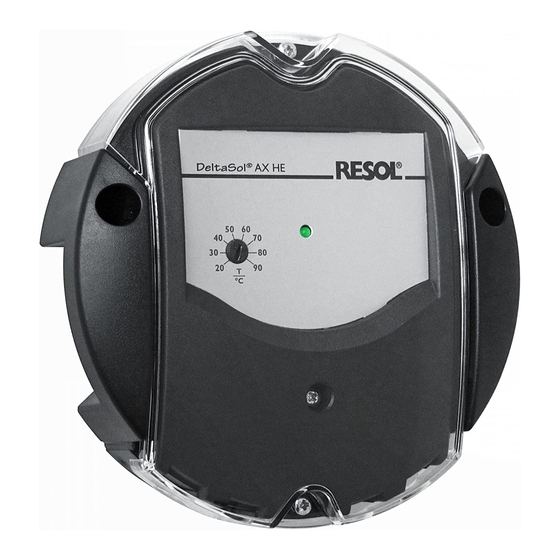
AX HE
DeltaSol
®
Differential temperature controller
Manual for the specialised craftsman
Installation
Operation
Functions and options
Troubleshooting
en
Thank you for buying this RESOL product.
Manual
Please read this manual carefully to get the best performance from this unit.
Please keep this manual safe.
www.resol.com
Advertisement
Table of Contents

Related Manuals for Resol DeltaSol AX HE


Summary of Contents for Resol DeltaSol AX HE
- Page 1 Differential temperature controller Manual for the specialised craftsman Installation Operation Functions and options Troubleshooting Thank you for buying this RESOL product. Manual Please read this manual carefully to get the best performance from this unit. Please keep this manual safe. www.resol.com...
- Page 2 Safety advice Description of symbols Please pay attention to the following safety advice in order to avoid danger and WARNING! Warnings are indicated with a warning triangle! damage to people and property. Î They contain information on how to avoid the danger described.
-
Page 3: Table Of Contents
DeltaSol AX HE differential temperature controller ® The DeltaSol AX HE controller is the simplest solution for all differen- Additionally, the controller offers an antifreeze function and an adjustable target ® tial controls. Equipped with an electromechanical relay and a PWM output, the temperature for minimum or maximum temperature limitation. -
Page 4: Overview
Overview Installation • Adjustable temperature difference 2 … 16 K, hysteresis 1.6 K Mounting • 1 PWM output for speed control of a high-efficiency pump Electric shock! WARNING! • Antifreeze function adjustable by DIP switch Upon opening the housing, live parts are exposed! •... - Page 5 In order to mount the device to a wall, carry out the following steps: 112mm Switch-on temperature difference potentiometre Minimum speed HE pump potentiometre Temperature limitation T4A fuse potentiometre PWM profile jumper Mains connection DIP switches Sensor 1, 2 PWM output Relay (load) Grounding terminal (common terminal block)
-
Page 6: Electrical Connection
Electrical connection Operation and function Electric shock! WARNING! Flashing codes Upon opening the housing, live parts are exposed! The operating control lamp indicates the current status of the controller. Î Always disconnect the device from power supply Colour Permanent Flashing Fast flashing before opening the housing! Green... -
Page 7: Switch-On Temperature Difference
Manual mode The DIP switches (A) can be used for activating (ON) or deactivating (OFF) the For commissioning or maintenance work, the relay following functions: can be permanently energised by means of the manual • Manual mode (DIP switch 1) mode. -
Page 8: Minimum Temperature Limitation
Minimum temperature limitation Examples Standard solar system with 1 store With DIP switch 4, the temperature limitation can be activated as a minimum temperature limitation. The The controller calculates the temperature difference limit temperature can be adjusted by means of the between collector sensor S1 and store sensor S2. -
Page 9: Heating Circuit Return Preheating
Heating circuit return preheating Heat exchange control The controller calculates the temperature difference When the temperature difference between sensor 1 between collector sensor S1 and store sensor S2. If (store 1) and sensor 2 (store 2) exceeds the adjust- the difference is larger than or identical to the adjust- ed value, the circulating pump will be activated. -
Page 10: Store Loading By Means Of A Solid Fuel Boiler
Store loading by means of a solid fuel boiler Accessories The controller calculates the temperature difference between solid fuel boiler sensor S1 and store sensor S2. The relay (RO) is energised when both switch-on conditions are fulfilled: • the temperature difference has exceeded the switch- on value •... - Page 11 1000 1252 1019 1271 1039 1290 1058 1309 1078 1328 1097 1347 1117 1366 1136 100 212 1385 1155 105 221 1404 1175 110 230 1423 1194 115 239 1442 Note: For answers to frequently asked questions (FAQ) see www.resol.com.
- Page 12 This mounting- and operation manual including all parts is copyrighted. Another some examples. They can only be used at your own risk. No liability is assumed for use outside the copyright requires the approval of RESOL – Elektronische Rege- incorrect, incomplete or false information and / or the resulting damages.
Need help?
Do you have a question about the DeltaSol AX HE and is the answer not in the manual?
Questions and answers