Table of Contents
Advertisement
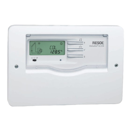
DeltaSol
Solar controller for standard solar systems
with electric backup heating
Manual for the
specialised craftsman
Installation
Operation
Functions and options
Troubleshooting
The Internet portal for easy and secure access
to your system data – www.vbus.net
Thank you for buying this RESOL product.
Please read this manual carefully to get the best performance from this unit.
Please keep this manual safe.
AL E HE
®
beginning with version 2.01
en
Manual
www.resol.com
Advertisement
Table of Contents

Related Manuals for Resol DeltaSol AL EHE


Summary of Contents for Resol DeltaSol AL EHE
- Page 1 Troubleshooting The Internet portal for easy and secure access to your system data – www.vbus.net Thank you for buying this RESOL product. Manual Please read this manual carefully to get the best performance from this unit. Please keep this manual safe.
- Page 2 Safety advice Target group Please pay attention to the following safety advice in order to avoid danger and These instructions are exclusively addressed to authorised skilled personnel. damage to people and property. Only qualified electricians are allowed to carry out electrical works. Danger of electric shock: Initial commissioning must be effected by authorised skilled personnel.
-
Page 3: Table Of Contents
Solar controller for standard solar systems with electric backup heating The DeltaSol AL E HE controller is especially designed for standard solar sys- ® tems with a high-efficiency pump and an electric backup heating. It is equipped with a PWM output and two high-current relays to which an electric immersion heater of up to 3 kW (230 V~) can be connected. -
Page 4: Overview
Overview • Direct connection of an electric immersion heater up to 3 kW (230 V~) Technical data • DHW heating with rapid heat-up and thermal disinfection Inputs: for 4 Pt1000 temperature sensors, thereof 1 x RCTT, 1 x Grundfos Direct •... -
Page 5: Installation
Installation Mounting WARNING! Electric shock! Upon opening the housing, live parts are exposed! Î Always disconnect the device from power supply before opening the housing! 0 Auto I Note 0 Auto I 0 Auto I Strong electromagnetic fields can impair the function of the device. Î... -
Page 6: Electrical Connection
Electrical connection The controller is supplied with power via a mains cable. The power supply of the WARNING! Electric shock! device must be 100 … 240 V~ (50 … 60 Hz). Upon opening the housing, live parts are exposed! The controller is equipped with 1 semiconductor relay to which a load such as Î... -
Page 7: Grundfos Direct Sensor
® /USB or VBus ® /LAN interface adapter (not included). Different PWM output, control signal solutions for visualisation and remote parameterisation are available on the web- PWM, GND site www.resol.com. PWM input, feedback signal Note More accessories on page 37. -
Page 8: Terminal Allocation With Cable Link
Terminal allocation with cable link The controller calculates the temperature difference between collector sensor Sensor S3 can optionally be used as the reference sensor for the thermal disinfec- S1 and store sensor S2. If the difference is larger than or identical to the adjusted tion function (OTD) or the store emergency shutdown option (OSEM). -
Page 9: Terminal Allocation Without Cable Link
Terminal allocation without cable link The controller calculates the temperature difference between collector sensor Sensor S3 can optionally be used as the reference sensor for the thermal disinfec- S1 and store sensor S2. If the difference is larger than or identical to the adjusted tion function (OTD) or the store emergency shutdown option (OSEM). -
Page 10: Operation And Function
Operation and function Buttons System-Monitoring-Display The controller is operated via the 3 buttons next to the display: Activating the rapid heat-up function (press and hold down button for 3 s) Button : Scrolling upwards, increasing adjustment values (press button briefly) The System-Monitoring-Display consists of 3 blocks: channel display, tool bar ⛁... - Page 11 3.2.2 Tool bar 3.2.3 System screen The system scheme is indicated on the System-Monitoring-Display. It consists of several system component symbols which are – depending on the current status of the system – either flashing or permanently shown. The additional symbols in the tool bar indicate the current system state. Permanently Flashing Status indications:...
-
Page 12: Slide Switch
Slide switch Shortcuts for backup heating off, rapid heat-up and holiday mode By means of the slide switch, the controller can be set to different operating modes: Slide switch position left ☼ • Backup heating off = ☼ (left) Backup heating off •... -
Page 13: Commissioning
Commissioning Commissioning 1. Language scrolling upwards (+) Î Adjust the desired menu language. LANG Language selection Ⓢ (selection / adjustment mode) Selection: dE, En, Fr, ES, It Factory setting: dE scrolling downwards (-) 2. Temperature unit Î Connect the device to the mains. Î... - Page 14 Commissioning Pump control type 7. Maximum speed Î Adjust the pump control type. Î Adjust the maximum speed for the corresponding pump. Pump control type Selection: OnOF, PULS, PSOL, PHEA Maximum speed Factory setting: PSOL Adjustment range: (10) 30 … 100 % The following types can be selected: Adjustment for Factory setting: 100 % standard pump without speed control...
-
Page 15: Control Parameters And Display Channels
Control parameters and display channels Channel overview Display channels Adjustment channels Channel Description Connection terminal Page Channel Description Factory setting Page INIT x* ODB initialisation active DT O x Switch-on temperature difference R1 6.0 K [12.0 °Ra] x* ODB filling time active DT F x Switch-off temperature difference R1 4.0 K [8.0 °Ra]... - Page 16 Adjustment channels Channel Description Factory setting Page BHMN s Thermostat comfort temperature 40 °C [110 °F] BH O s Switch-on temperature for thermostat 40 °C [110 °F] BH F s Switch-off temperature for thermostat 45 °C [120 °F] t1 O s Thermostat switch-on time 1 00:00 t1 F...
-
Page 17: Channel Overview
Channel overview Display channels Note: Indication of rapid heat-up and days of absence The display and adjustment channels as well as the adjustment ranges de- Rapid heat-up pend on the system selected, the functions and options as well as on the system components connected to the controller. - Page 18 Display of store temperatures Display of further temperatures TST, TSTB, TSTT, TDIS TFL, TR Further measured temperatures Store temperatures Display range: -40 … +260 °C [-40 … +500 °F] Display range: -40 … +260 °C [-40 … +500 °F] Indicates the current temperature at the corresponding sensor. Indicates the store temperatures.
- Page 19 Display of heat quantity SDIS kWh/MWh Display of starting time Heat quantity in kWh / MWh Display range: 00:00 … 24:00 (hh:mm) Display channel If the thermal disinfection option (OTD) is activated and a starting delay time has Indicates the heat quantity produced in the system. been adjusted, the adjusted starting time is displayed as SDIS (flashing).
-
Page 20: Adjustment Channels
Operating hours counter Adjustment channels ∆T control h P / h P1 / h P2 Operating hours counter DT O Display channel Switch-on temperature difference The operating hours counter accumulates the operating hours of the correspond- Adjustment range: 1.0 … 20.0 K [2.0 … 40.0 °Ra] ing relays (h P / h P1 / h P2). - Page 21 Speed control DT S Pump control type Set temperature difference Selection: OnOF, PULS, PSOL, PHEA Adjustment range: 1.5 … 30.0 K [3.0 … 60.0 °Ra] Factory setting: PSOL Factory setting: 10.0 K [20.0 °Ra] With this parameter, the pump control type can be adjusted. The following types can be selected: Adjustment for standard pump without speed control •...
- Page 22 Maximum speed Err5: The pump stops, but is not operable, internal cause electronics / pump is stuck Err6: PWM feedback signal connection defective Note If there is an error, the flow rate will not be indicated and the heat quan- Maximum speed tity measurement will not be carried out.
- Page 23 Store emergency shutdown Cooling functions In the following the 3 cooling functions – collector cooling, system cooling and store cooling – are described in detail. The following note is valid for all 3 cooling functions: Note: The cooling functions will not become active as long as solar loading is OSEM possible.
- Page 24 System cooling Store cooling OSTC OSYC System cooling option Store cooling option Adjustment range: OFF / ON Adjustment range: OFF / ON Factory setting: OFF Factory setting: OFF OHOL DTCO Holiday cooling option Switch-on temperature difference Adjustment range: OFF / ON Adjustment range: 1.0 …...
- Page 25 Antifreeze function When the holiday cooling function is activated, ☼ and ⚠ (flashing) are shown on the display. If the holiday cooling function is active, ⓵, ☼ and ⚠ are displayed (flashing). Note: The holiday cooling will only become active when the holiday mode is Antifreeze function option triggered by means of button ⛁...
- Page 26 Tube collector function TCRU Tube collector option Tube collector function runtime Adjustment range: 5 … 500 s Adjustment range: OFF / ON Factory setting: 30 s Factory setting: OFF TCIN TCST Tube collector function standstill interval Tube collector function starting time Adjustment range: 1 …...
- Page 27 Heat quantity measurement The VFD Grundfos Direct Sensor™ can optionally be used for measuring the tem- perature: The heat quantity measurement can be carried out in 3 different ways (see below): with a fixed flow rate value, with a VFD Grundfos Direct Sensor™ or with a PWM Î...
- Page 28 Note: The thermostat switch-on temperature can only be lower than or equal to the thermostat switch-off temperature. The thermostat function can be used for backup heating. S3 is used as the refer- MEDT ence sensor. Heat transfer fluid If the temperature falls below the thermostat switch-on temperature BH O, relay Adjustment range: 0 …...
- Page 29 If the thermostat function is supposed to run from 06:00 a.m. to 09:00 a.m. only, Drainback option adjust t1 O to 06:00 a.m. and t1 F to 09:00 a.m. Note: If the switch-on and switch-off times of a time frame are set to an identical value, A drainback system requires additional components such as a holding the time frame will be inactive.
- Page 30 Time period – switch-on condition Thermal disinfection of the upper DHW zone tDTO Time period – switch-on condition Therm. disinfection function Adjustment range: 1 … 100 s Adjustment range: OFF / ON Factory setting: 60 s Factory setting: OFF The parameter tDTO is used for adjusting the time period during which the switch-on condition must be permanently fulfilled.
- Page 31 Operating mode For thermal disinfection, the temperature at the reference sensor will be moni- tored. Protection is ensured when, during the monitoring period, the disinfection temperature is continuously exceeded for the entire disinfection period. The monitoring period starts as soon as the temperature at the reference sensor falls below the disinfection temperature.
- Page 32 Language Reset LANG RESE Language selection Reset function Selection: dE, En, Fr, ES, It By means of the reset function, all adjustments can be set back to their factory Factory setting: dE settings. In this adjustment channel the menu language can be selected. Î...
-
Page 33: Rctt Remote Control (Accessory)
RCTT Remote control (accessory) The RCTT Remote control enables rapid heat-up activation via the button with- out having to access the controller menu. It is connected to the controller with a 3-wire cable (see page 6). If the button of the RCTT is pressed, rapid heat-up will be activated on the con- troller. -
Page 34: Troubleshooting
Fuse Pt1000 Pt1000 1213 1232 1000 1252 1019 1271 1039 1290 Note 1058 1309 For answers to frequently asked questions (FAQ) see www.resol.com. 1078 1328 1097 1347 1117 1366 1136 100 212 1385 1155 105 221 1404 1175 110 230... - Page 35 Operating control LED is permanently off Pump starts up very late. Switch-on temperature difference If the operating control LED is off, check the power supply of the controller. Is ∆Ton too large? it disconnected? Change ∆Ton and ∆Toff corre- spondingly. The fuse of the controller could Check the supply line and recon- Non-ideal position of the collector...
- Page 36 The solar circuit pump does not work, although the collector is considerably Insulation close enough to the warmer than the store store? Is the operating control LED on? Replace insulation or increase it. There is no current; check fuses / Are the store connections replace them and check power insulated?
-
Page 37: Accessories
Accessories Sensors SD3 Smart Display / GA3 Large Display AM1 Alarm module Overvoltage protection device KM2 Communication module RCTT Remote control DL2 Datalogger VBus / USB & VBus / LAN ® ® interface adapters DL3 Datalogger... -
Page 38: Sensors
Sensors Sensors RCTT Remote control The product range includes high-precision platinum temperature sensors, flatscrew The RCTT Remote control enables rapid heat-up activation via the button without sensors, outdoor temperature sensors, indoor temperature sensors, cylindrical having to access the controller menu (see page 33). clip-on sensors, also as complete sensors with immersion sleeve. -
Page 39: Index
Index Accessories......................... 37 Operating hours counter ....................20 Antifreeze function ......................25 Pump control type ......................21 Backup heating ........................28 PWM feedback ........................22 Backup heating suppression .................... 28 PWM interface........................7 PWM signal ........................... 7 Cable link ..........................8 Collector cooling ...................... - Page 40 This mounting- and operation manual including all parts is copyrighted. Another some examples. They can only be used at your own risk. No liability is assumed for use outside the copyright requires the approval of RESOL – Elektronische Rege- incorrect, incomplete or false information and / or the resulting damages.
Need help?
Do you have a question about the DeltaSol AL EHE and is the answer not in the manual?
Questions and answers