
Related Manuals for Yamaha TMAX ABS Series


Summary of Contents for Yamaha TMAX ABS Series
- Page 1 OWNER’S MANUAL TMAX ABS MOTORCYCLE Read this manual carefully before oper- ating this vehicle. XP530-A XP530D-A BV1-28199-E2...
- Page 2 Frequency band: 433.92 MHz The maximum radio frequency power: 10 mW Manufacturer: MITSUBISHI ELECTRIC CORPORATION, HIMEJI WORKS 840, Chiyoda-machi, Himeji, Hyogo 670-8677, Japan Importer: YAMAHA MOTOR EUROPE N.V. Koolhovenlaan 101, 1119 NC Schiphol-Rijk, 1117 ZN, Schiphol, the Netherlands For South Africa...
- Page 3 EAU79574 For Europe This model is equipped with My TMAX Connect GPS system. This system must be activated before it can be used. Please refer to the Vodafone Customer Portal User Guide for instructions on how to register and activate the system. www.my-tmax-connect.eu...
- Page 4 If you have any further questions, do not hesitate to con- tact your Yamaha dealer. The Yamaha team wishes you many safe and pleasant rides. So, remember to put safety first! Yamaha continually seeks advancements in product design and quality. There-...
- Page 5 *Product and specifications are subject to change without notice. EAU10201 XP530-A/XP530D-A OWNER’S MANUAL ©2019 by Yamaha Motor Co., Ltd. 1st edition, August 2018 All rights reserved. Any reprinting or unauthorized use without the written permission of Yamaha Motor Co., Ltd.
-
Page 6: Table Of Contents
Table of contents Safety information ......1-1 Rear view mirrors ......5-26 Further safe-riding points....1-5 Shock absorber assembly ..... 5-26 Auxiliary DC jack ......5-28 Description ........2-1 Sidestand ........5-29 Left view ..........2-1 Ignition circuit cut-off system ..5-29 Right view ........2-2 For your safety –... - Page 7 Table of contents Checking the rear brake lock..8-21 Checking the front and rear brake pads ........... 8-22 Checking the brake fluid level ..8-22 Changing the brake fluid ....8-23 Drive belt slack ......8-24 Checking and lubricating the cables.........
-
Page 8: Safety Information
Safety information EAU1026B for a list of pre-operation checks. This scooter is designed to carry the operator and a passenger. Be a Responsible Owner The failure of motorists to detect As the vehicle’s owner, you are respon- and recognize scooters in traffic is sible for the safe and proper operation the predominating cause of auto- of your scooter. - Page 9 Safety information Protective Apparel help you to avoid an accident. • We recommend that you prac- The majority of fatalities from scooter tice riding your scooter where accidents are the result of head inju- there is no traffic until you have ries.
- Page 10 The total weight of the operator, pas- senger, accessories and cargo must Yamaha accessories, which are avail- not exceed the maximum load limit. able only from a Yamaha dealer, have Operation of an overloaded vehicle been designed, tested, and approved could cause an accident.
- Page 11 Yamaha or should be kept to a minimum. • Bulky or large accessories may modifications not specifically recom- mended by Yamaha, even if sold and seriously affect the stability of installed by a Yamaha dealer. the scooter due to aerodynamic effects.
-
Page 12: Further Safe-Riding Points
Safety information Transporting the Scooter EAU57600 Further safe-riding points Be sure to observe following instruc- Be sure to signal clearly when tions before transporting the scooter in making turns. another vehicle. Braking can be extremely difficult Remove all loose items from the on a wet road. -
Page 13: Description
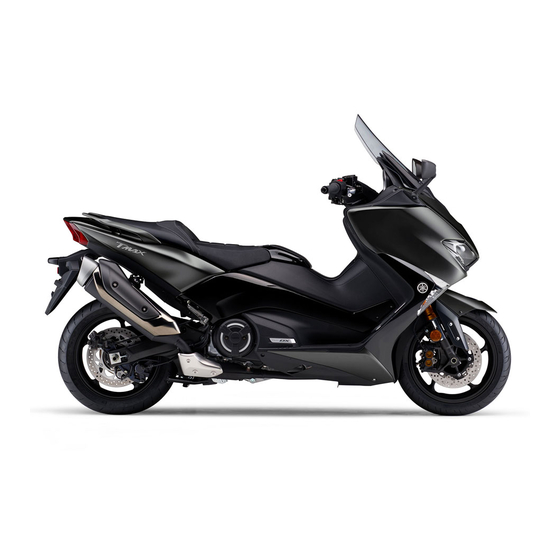
Description EAU63371 Left view 1. Battery (page 8-28) 2. Fuel tank cap (page 5-19) 3. Rear storage compartment (page 5-23) 4. Engine oil filler cap (page 8-10) 5. Grab bar (page 7-3) 6. Sidestand (page 5-29) 7. Engine oil drain bolt (page 8-10) 8. -
Page 14: Right View
Description EAU63391 Right view 1. Tool kit (page 8-2) 2. Air filter element (page 8-15) 3. Windshield (page 5-24/5-7) 4. Fuses (page 8-29) 5. Centerstand (page 8-26) -
Page 15: Controls And Instruments
Description EAU63401 Controls and instruments 10, 11 1. Rear brake lever (page 5-17) 2. Left handlebar switches (page 5-1) 3. Rear brake lock lever (page 5-18) 4. Speedometer (page 5-4) 5. Multi-function display (page 5-5) 6. Tachometer (page 5-4) 7. Right handlebar switches (page 5-1) 8. -
Page 16: Smart Key System
Smart key system EAU77201 Smart key system The smart key system enables the ve- hicle to be operated without using a mechanical key. EWA14704 WARNING Keep implanted pacemakers or cardiac defibrillators, as well as other electric medical devices away from the vehicle mounted 1. -
Page 17: Operating Range Of The Smart Key
Smart key system EAU77213 Operating range of the smart key system The operating range of the smart key system is about 80 cm (31.5 in) from the center of the handlebars. 1. “ / ” switch 2. “OFF/LOCK” switch ECA15764 NOTICE The smart key system uses weak ra- dio waves. -
Page 18: Handling Of The Smart Key And Mechanical Key
Smart key system municate with the vehicle, all EAU61646 Handling of the smart key and switches will be temporarily dis- mechanical key abled. Included with the vehicle is one smart Placing the smart key in the front key (with a built-in mechanical key) and or rear storage compartment may one spare mechanical key with an iden- block communication between the... - Page 19 Do not leave the smart key in a system still does not operate, have a place exposed to direct sun- Yamaha dealer check the vehicle. light, high temperature or high humidity. Do not grind or attempt to mod- ...
-
Page 20: Smart Key
Smart key system EAU77223 smart key system, and then once more Smart key to turn on the vehicle power. To use the mechanical key Pull out the mechanical key from the smart key body. After using the me- chanical key, insert it back into the smart key. -
Page 21: Replacing The Smart Key Battery
Smart key system or fire. EAU79071 Replacing the smart key battery Chemical Burn Hazard - do not in- gest the battery. Replace the battery in the following sit- If the battery is swallowed, it can uations. cause severe internal burns in The smart key system indicator just 2 hours and can lead to light flashes for about 20 seconds... - Page 22 Smart key system 2. Remove the battery cover and O- 1. Battery ring. 2. O-ring 3. Battery cover 5. Install the O-ring and battery cov- 6. Gently snap the smart key case closed. 1. Battery cover 2. O-ring 3. Remove the battery. Dispose of the removed battery in ac- cordance with local regulations.
-
Page 23: Powering On The Vehicle
1. “ON/ ” switch ing, have a Yamaha dealer check the 2. Upon authentication of the smart smart key system. key, the beeper will sound twice and the smart key system indicator 3. -
Page 24: Powering Off The Vehicle
Smart key system EAU78031 ering off the vehicle again. Powering off the vehicle To turn the vehicle power off and stop Without the smart key, the vehicle pow- the engine if it is running, press the er can be turned off by pressing the “OFF/LOCK”... -
Page 25: How To Lock The Steering
Smart key system EAU80000 EAU78052 How to lock the steering How to lock the centerstand After moving the vehicle to a safe park- Park the vehicle on a firm level surface ing place, turn off the power of the vehi- and then place it on the centerstand. -
Page 26: Storage Compartment And Fuel Tank Access
Smart key system EAU81290 Storage compartment and fuel tank access To open the seat 1. Place the vehicle on the center- stand. 2. Briefly press the “ / ” switch. Upon authentication of the smart key, the beeper will sound twice. To close the seat Fold the seat down, and then push it to lock it in place. - Page 27 Smart key system 1. Fuel tank cap lid To close the front storage compart- ment lid To close the fuel tank cap lid Push the lid into the original position. Push the lid to the original position. To open the front storage compart- ment lid With the smart key on and in operating range, briefly press the “...
-
Page 28: Parking Mode
Smart key system EAU80841 Parking mode The steering is locked, and the hazard lights and turn signal lights can be turned on, but all other electrical sys- tems are off. To enter parking mode 1. Lock the steering. (See page 3-10.) 2. -
Page 29: Special Features
Special features EAU77263 Cruise control system (XP530D-A) The cruise control system is designed to maintain a set cruising speed be- tween about 50 km/h (31 mi/h) and 140 km/h (87 mi/h). EWA16341 WARNING Improper use of the cruise con- 1. - Page 30 Special features traveling speed using the throttle. After EWA16351 WARNING you have accelerated, you can set a It is dangerous to use the resume new cruising speed by pushing the function when the previously set “SET–” side of the setting switch. If you cruising speed is too high for cur- do not set a new cruising speed, when rent conditions.
-
Page 31: D-Mode (Drive Mode)
Special features matically deactivated, please stop and EAU81390 D-mode (drive mode) confirm that your vehicle is in good op- D-mode is an electronically controlled erating condition before continuing on. engine performance system with two When traveling on roads with steep mode selections (touring mode “T”... -
Page 32: Traction Control System
Special features Sports mode “S” EAU77281 Traction control system This mode offers a sportier engine re- The traction control system (TCS) sponse in the low- to mid-speed range helps maintain traction when accelerat- compared to the touring mode. ing on slippery surfaces, such as un- paved or wet roads. - Page 33 Turn the traction control system off to check the vehicle as soon as possible. help free the rear wheel if the vehicle 4. Have a Yamaha dealer check the gets stuck in mud, sand, or other soft vehicle and turn off the “...
-
Page 34: Instrument And Control Functions
Instrument and control functions EAU77490 Handlebar switches When the switch is set to low Left beam, the inner two headlights come on. When the switch is set to high beam, all four headlights come on. EAU66040 Turn signal switch “ ”... -
Page 35: Indicator Lights And Warning Lights
Instrument and control functions hazard lights (simultaneous flashing of EAU77122 Indicator lights and warning all turn signal lights). lights The hazard lights are used in case of an emergency or to warn other drivers when your vehicle is stopped where it 4 5 6 might be a traffic hazard. - Page 36 Instrument and control functions cal circuits as soon as possible. have a Yamaha dealer check the on- board diagnostic system. The electrical circuit of the warning light can be checked by turning the vehicle The ABS warning light may come on power on.
-
Page 37: Speedometer
Instrument and control functions EAU77131 EAU77141 Speedometer Tachometer 1. Speedometer 1. Tachometer 2. High-r/min zone The speedometer shows the vehicle’s The tachometer shows the engine traveling speed. speed in crankshaft revolutions per When the vehicle power is turned on, minute (r/min). the speedometer needle will sweep When the vehicle power is turned on, across the speed range and return to... -
Page 38: Multi-Function Display
If a problem is detected in the fuel me- ter electrical circuit, the fuel meter will flash repeatedly. Have a Yamaha deal- er check the vehicle. 1. Oil change indicator “Oil” 2. V-belt replacement indicator “V-Belt”... - Page 39 Instrument and control functions Drive mode display changes in the weather and engine load. If the top segment starts flashing, the information display automatically changes to “C-TEMP” and “Hi” flashes. Stop the vehicle and let the engine cool. (See page 8-36.) The information display cannot be changed while the engine is overheat- ing.
- Page 40 Instrument and control functions Oil change indicator Function selection Push the “MENU” switch for one sec- 1. Oil change indicator “Oil” ond to switch among the grip warmer This indicator flashes at the initial 1000 adjusting function, seat heater adjust- km (600 mi), then at 5000 km (3000 mi) ing function, and information display and every 5000 km (3000 mi) thereafter...
- Page 41 Instrument and control functions switch. To decrease the seat heater temperature, push the “ ” side of the Setting Display select switch. ECA23980 NOTICE Be sure to wear protective cloth- Middle ing that covers your hip and legs when using the seat heater. High If the ambient temperature is 20 ...
- Page 42 Instrument and control functions The odometer shows the total distance switch the display in the following order: traveled by the vehicle. F-TRIP Display–1 Display–2 Tripmeters: Display–3 F-TRIP If you do not reset the fuel reserve trip- meter manually, it will reset automati- cally after refueling and traveling 5 km (3 mi).
- Page 43 If there is a malfunction, “– –.–” will “L/100km”. For UK-spec vehicles: be continuously displayed. Have a “MPG”. (See page 5-13.) Yamaha dealer check the vehicle. To reset the average fuel consumption, use the select switch to select the infor- Setting mode mation display page that contains the average fuel consumption display.
- Page 44 Instrument and control functions Menu items Category Description This function allows you to set the low, middle, and Grip Warmer high settings to 10 temperature levels. This function allows you to set the low, middle, and Seat Heater high settings to 10 temperature levels.
- Page 45 Instrument and control functions dure that was used for the high set- ting. 5. When you finished changing the settings, use the select switch to highlight “ ”, and then push the “MENU” switch to return to the menu screen. Seat heater settings 1.
- Page 46 Instrument and control functions 3. To set the traction control system 2. Push the “MENU” switch, and then to “OFF”, push the select switch use the select switch to select the “ ” side for 2 seconds. item to reset. 4.
- Page 47 Instrument and control functions Selecting the display items function does not indicate on setting mode display and cannot be selected. 1. Use the select switch to highlight “Display Change”. 1. Use the select switch to highlight “Unit”. 2. Push the “MENU” switch, use the select switch to highlight the dis- 2.
- Page 48 Instrument and control functions A.TEMP TRIP-1 TRIP-2 CRNT.F F.AVG RANGE 4. Use the select switch to select the 2. Push the “MENU” switch. item to show, and then push the 3. Use the select switch to select the “MENU” switch. desired brightness level.
- Page 49 Instrument and control functions use the select switch to set the “YES”, and then push the “MENU” hours. switch. All items are reset to facto- ry preset or default settings. 4. Push the “MENU” switch, and the minute digits start flashing. The odometer, clock, maintenance counter item “Oil”...
-
Page 50: Front Brake Lever
Instrument and control functions EAU44914 EAU44924 Front brake lever Rear brake lever 1. Front brake lever 1. Rear brake lever 2. Brake lever position adjusting dial 2. Brake lever position adjusting dial 3. “ ” mark 3. “ ” mark 4. -
Page 51: Rear Brake Lock Lever
Instrument and control functions EAU63230 EAU65582 Rear brake lock lever Anti-lock brake system (ABS) This model’s ABS features a dual elec- tronic control system, which acts on the front and rear brakes independently. Operate the brakes with ABS as you would conventional brakes. -
Page 52: Fuel Tank Cap
Instrument and control functions special tools are required, so EAU77324 Fuel tank cap please consult your Yamaha deal- To access the fuel tank, open the fuel tank cap lid. (See page 3-11.) ECA20100 NOTICE Be careful not to damage the wheel sensor or wheel sensor rotor;... -
Page 53: Fuel
Instrument and control functions EAU13222 Fuel Make sure there is sufficient gasoline in the tank. EWA10882 WARNING Gasoline and gasoline vapors are extremely flammable. To avoid fires and explosions and to reduce the risk of injury when refueling, follow these instructions. 1. - Page 54 Check that gasoline nozzle has the wash with soap and water. If gaso- same identifier when fueling. line spills on your clothing, change Your Yamaha engine has been de- your clothes. signed to use regular unleaded gaso- line with a research octane number of 95 or higher.
-
Page 55: Fuel Tank Overflow Hose
Instrument and control functions EAU58301 EAU13434 Fuel tank overflow hose Catalytic converter This model is equipped with a catalytic converter in the exhaust system. EWA10863 WARNING The exhaust system is hot after op- eration. To prevent a fire hazard or burns: Do not park the vehicle near ... -
Page 56: Storage Compartments
Instrument and control functions EAU80862 Storage compartments The storage compartments have elec- tronic locks. (See page 3-11.) Front storage compartment To open the storage compartment, press the button. 1. Lid Rear storage compartment This storage compartment was de- signed to hold one full-faced helmet or two 3/4-faced helmets. -
Page 57: Windshield (Xp530-A)
Instrument and control functions ECA15964 EAU81440 Windshield (XP530-A) NOTICE The windshield height can be changed Do not leave the seat open for to one of two positions. an extended period of time, oth- erwise the light may cause the battery to discharge. - Page 58 Instrument and control functions Tightening torque: Windshield screw: 10 N·m (1.0 kgf·m, 7.4 lb·ft) 5. Place the screw access covers, and then install the quick fasten- ers. To install the quick fastener, set it with its screwed portion pulled out from the 2.
-
Page 59: Rear View Mirrors
back to their original position before worn-out shock absorber as- riding. sembly yourself. Take the shock absorber assembly to a Yamaha dealer for any service. ECA10102 NOTICE To avoid damaging the mechanism, do not attempt to turn beyond the maximum or minimum settings. - Page 60 Instrument and control functions soften the suspension, turn the adjust- ing ring in direction (b). 1. Rebound damping force adjusting screw Rebound damping setting: 1. Special wrench Minimum (soft): 2. Position indicator 3 (XP530D-A) turns in direction 3. Spring preload adjusting ring (b)* Standard: ...
-
Page 61: Auxiliary Dc Jack
Instrument and control functions EAU77352 Auxiliary DC jack This model is equipped with a 12 V aux- iliary DC jack. The DC jack is located in- side the front storage compartment. 1. Auxiliary DC jack cap EWA14361 WARNING To prevent electrical shock or short- circuiting, make sure that the cap is 1. -
Page 62: Sidestand
Therefore, check this system regularly and have a Yamaha dealer repair it if it does not function properly. 5-29... - Page 63 “ ”. • If a malfunction is noted, have a 3. Turn the vehicle power on. Yamaha dealer check the system 4. Keep the front or rear brake applied. before riding. 5. Push the “ON/ ” switch.
-
Page 64: For Your Safety - Pre-Operation Checks
Do not operate the vehicle if you find any problem. If a problem cannot be corrected by the procedures provided in this manual, have the vehicle inspected by a Yamaha dealer. Before using this vehicle, check the following points:... - Page 65 • Tighten if necessary. Instruments, lights, • Check operation. — signals and switches • Correct if necessary. • Check operation of ignition circuit cut-off system. Sidestand switch • If system is not working correctly, have Yamaha dealer 5-29 check vehicle.
-
Page 66: Operation And Important Riding Points
This model is equipped with: there is a control or function you do not a lean angle sensor to stop the en- understand, ask your Yamaha dealer. gine in case of a turnover. In this EWA10272 case, the engine trouble warning... -
Page 67: Starting The Engine
Operation and important riding points warning and indicator light circuit EAU77082 Starting the engine check. ECA10251 NOTICE 3. Close the throttle completely. 4. Start the engine by pushing the See page 7-5 for engine break-in in- “ON/ ” switch while applying the structions prior to operating the ve- front or rear brake. -
Page 68: Starting Off
Operation and important riding points EAU45093 EAU16782 Starting off Acceleration and deceleration 1. While pulling the rear brake lever with your left hand and holding the grab bar with your right hand, push the scooter off the centerstand. The speed can be adjusted by opening and closing the throttle. -
Page 69: Braking
Operation and important riding points Rear EAU16794 Braking EWA10301 WARNING Avoid braking hard or suddenly (especially when leaning over to one side), otherwise the scooter may skid or overturn. Railroad crossings, streetcar rails, iron plates on road con- struction sites, and manhole covers become extremely slip- pery when wet. -
Page 70: Tips For Reducing Fuel Consumption
The vehicle can now be operated nor- mally. ECA10311 NOTICE Keep the engine speed out of the tachometer red zone. If any engine trouble should oc- cur during the engine break-in period, immediately have a Yamaha dealer check the vehi- cle. -
Page 71: Parking
Operation and important riding points EAU77960 Parking When parking, turn the vehicle power off and then the smart key off. When leaving the vehicle, make sure you apply the steering lock and center- stand lock. Take the smart key with you. -
Page 72: Periodic Maintenance And Adjustment
If you are not familiar with vehicle ser- vice, have a Yamaha dealer perform service. EWA15123 WARNING Turn off the engine when performing... -
Page 73: Tool Kit
However, a torque wrench and other tools are necessary to perform certain maintenance work correctly. If you do not have the tools or experi- ence required for a particular job, have your Yamaha dealer perform it for you. -
Page 74: Periodic Maintenance Charts
Periodic maintenance and adjustment EAU71033 Periodic maintenance charts Items marked with an asterisk should be performed by your Yamaha dealer because these items require special tools, data, and technical skills. From 50000 km (30000 mi), repeat the maintenance intervals starting from 10000 km (6000 mi). -
Page 75: General Maintenance And Lubrication Chart
X 1000 km X 1000 mi • Perform dynamic inspection Diagnostic system using Yamaha diagnostic tool. check • Check the error codes. 2 * Air filter element • Replace. • Clean. - Page 76 Periodic maintenance and adjustment ODOMETER CHECK OR READINGS MAINTENANCE JOB ITEM X 1000 km X 1000 mi • Check belt condition. At the initial interval and every • Replace if damaged. 10000 km (6000 mi) until 40000 13 * Drive belt •...
- Page 77 Periodic maintenance and adjustment ODOMETER CHECK OR READINGS MAINTENANCE JOB ITEM X 1000 km X 1000 mi • Check coolant level and vehicle for coolant leakage. 25 * Cooling system • Change. Every 3 years When the V-belt replacement 26 * V-belt •...
-
Page 78: Removing And Installing Panels
Periodic maintenance and adjustment EAU18773 Removing and installing panels The panels shown need to be removed to perform some of the maintenance jobs described in this chapter. Refer to this section each time a panel needs to be removed and installed. 1. - Page 79 Periodic maintenance and adjustment and then install the screw. Panel C To remove the panel Remove the screws, and then pull the panel outward. 3. Install the screws. Panel B To remove the panel 1. Remove the screw. 1. Screw 2.
-
Page 80: Checking The Spark Plugs
Do not attempt to diagnose 13 N·m (1.3 kgf·m, 9.6 lb·ft) such problems yourself. Instead, have a Yamaha dealer check the vehicle. If a spark plug shows signs of electrode If a torque wrench is not available when erosion and excessive carbon or other installing a spark plug, a good estimate deposits, it should be replaced. -
Page 81: Canister
Periodic maintenance and adjustment EAU36112 EAU77364 Canister Engine oil and oil filter cartridge The engine oil level should be checked before each ride. In addition, the oil must be changed and the oil filter car- tridge replaced at the intervals speci- fied in the periodic maintenance and lubrication chart. - Page 82 1. Oil filter wrench 2. Oil filter cartridge An oil filter wrench is available at a Yamaha dealer. 7. Apply a thin coat of clean engine oil to the O-ring of the new oil filter cartridge. 1. Engine oil filler cap 1.
- Page 83 Periodic maintenance and adjustment Engine oil: Recommended brand: YAMALUBE SAE viscosity grades: 10W-40 Recommended engine oil grade: API service SG type or higher, JASO standard MA Oil quantity: Oil change: 2.60 L (2.75 US qt, 2.29 Imp.qt) 1. Torque wrench With oil filter removal: 2.90 L (3.07 US qt, 2.55 Imp.qt) Tightening torque:...
-
Page 84: Why Yamalube
Thus, Yamalube mineral, If genuine Yamaha coolant is not avail- semisynthetic and synthetic oils have able, use an ethylene glycol antifreeze their own distinct characters and value. - Page 85 If water has been 5. Remove the coolant reservoir cov- added to the coolant, have a er by removing the screws. Yamaha dealer check the anti- freeze content of the coolant as soon as possible, otherwise the effectiveness of the coolant will be reduced.
-
Page 86: Engine Air Filter Element
Periodic maintenance and adjustment WARNING! Never attempt to remove EAU52032 Engine air filter element the radiator cap when the engine is The engine air filter element should be hot. [EWA10382] replaced at the intervals specified in the periodic maintenance chart. Replace the air filter element more frequently if you often ride in wet or dusty condi- tions. -
Page 87: Checking The Engine Idling Speed
[ECA10482] Check the engine idling speed and, if 5. Install the air filter case cover by in- necessary, have it corrected by a stalling the screws. Yamaha dealer. 6. Install the panel. Engine idling speed: 1100–1300 r/min 8-16... -
Page 88: Checking The Throttle Grip Free Play
This service must be performed when 1. Throttle grip free play the engine is cold. Throttle grip free play: 1.0–3.0 mm (0.04–0.12 in) Periodically check the throttle grip free play and, if necessary, have a Yamaha dealer adjust it. 8-17... -
Page 89: Tires
The tires must be checked before each ride. If the center tread depth reaches the specified limit, if the tire has a nail or glass fragments in it, or if the sidewall is cracked, have a Yamaha dealer re- place the tire immediately. 8-18... - Page 90 Always make sure that the valve EWA10472 caps are securely installed to WARNING prevent air pressure leakage. Have a Yamaha dealer replace Use only the tire valves and excessively worn tires. Besides valve cores listed below to being illegal, operating the vehi- avoid tire deflation during a ride.
-
Page 91: Cast Wheels
The wheel rims should be checked for cracks, bends, warpage or oth- er damage before each ride. If any damage is found, have a Yamaha dealer replace the wheel. Do not attempt even the smallest repair to the wheel. A deformed or cracked wheel must be replaced. -
Page 92: Adjusting The Rear Brake Lock Cable
If the indicator has 43–45 mm (1.69–1.77 in) passed the wear indicator groove, Periodically check the rear brake lock have a Yamaha dealer check the cable length and adjust if necessary. rear brake lock. 1. Release the rear brake lock lever. -
Page 93: Checking The Front And Rear Brake Pads
1. Minimum level mark have a Yamaha dealer replace the As the brake pads wear, it is normal for brake pads as a set. the brake fluid level to gradually go down. -
Page 94: Changing The Brake Fluid
A low brake fluid level may indicate EAU22734 Changing the brake fluid worn brake pads or brake system Have a Yamaha dealer change the leakage; therefore, be sure to brake fluid every 2 years. In addition, check the brake pads for wear and have the seals of the master cylinders the brake system for leakage. -
Page 95: Drive Belt Slack
Drive belt slack Checking and lubricating the cables The drive belt slack should be checked and adjusted by a Yamaha dealer at The operation of all control cables and the intervals specified in the periodic the condition of the cables should be maintenance and lubrication chart. -
Page 96: Checking And Lubricating The Throttle Grip And Cable
Front brake lever be checked before each ride. In addi- tion, the cable should be lubricated by a Yamaha dealer at the intervals speci- fied in the periodic maintenance chart. The throttle cable is equipped with a rubber cover. Make sure that the cover is securely installed. -
Page 97: Checking And Lubricating The Centerstand And Sidestand
EWA10742 WARNING If the centerstand or sidestand does not move up and down smoothly, have a Yamaha dealer check or re- pair it. Otherwise, the centerstand or ECA10591 sidestand could contact the ground NOTICE and distract the operator, resulting If any damage is found or the front in a possible loss of control. -
Page 98: Checking The Steering
If there is play in the wheel ward and backward. If any free hub or if the wheel does not turn play can be felt, have a Yamaha smoothly, have a Yamaha dealer check dealer check or repair the steering. -
Page 99: Battery
IES OUT OF THE REACH OF CHILDREN. To charge the battery 1. Negative battery lead (black) Have a Yamaha dealer charge the bat- 2. Battery tery as soon as possible if it seems to 3. Positive battery lead (red) have discharged. Keep in mind that the The battery is located under panel B. -
Page 100: Replacing The Fuses
Periodic maintenance and adjustment ing the battery, connect the EAU81471 Replacing the fuses positive lead before connecting The main fuse box and the fuse boxes, the negative lead. [ECA21910] which contain the fuses for the individu- 4. After installation, make sure that al circuits, are located under panel A. - Page 101 Periodic maintenance and adjustment (XP530D-A) 1 2 3 7 6 5 1. ABS control unit fuse 1. Spare fuse 2. Auxiliary DC jack fuse 2. Windshield motor fuse 3. Headlight fuse 3. Signaling system fuse 4. Spare fuse 4. Ignition fuse 5.
-
Page 102: Vehicle Lights
LED lighting. If a light ABS control unit fuse: does not come on, check the fuses and 7.5 A then have a Yamaha dealer check the ABS motor fuse: vehicle. 30.0 A If a front turn signal light or license plate ABS solenoid fuse: 15.0 A... -
Page 103: Replacing A Front Turn Signal Light Bulb
Periodic maintenance and adjustment EAU52323 EAU81491 Replacing a front turn signal Replacing the license plate light bulb light bulb 1. Remove the turn signal light bulb 1. Remove the nuts securing the li- socket (together with the bulb) by cense plate light unit. turning it counterclockwise. -
Page 104: Troubleshooting
Yamaha vehicle. Be sure to use only genuine Yamaha replacement parts. Although imitation parts may look similar to genuine parts, they are often inferior in quality, have a shorter service life, and can lead to an expensive repair bill later on. - Page 105 (See page 8-28.) If the smart key system does not work after checking the above items, have a Yamaha dealer check the smart key system. See Emergency mode on page 8-37 for information on starting the engine with- out the smart key.
-
Page 106: Troubleshooting Charts
Check the vehicle. compression. 4. Compression The engine does not start. There is compression. Have a Yamaha dealer check the vehicle. Operate the electric starter. There is no Have a Yamaha dealer check the vehicle. compression. 8-35... - Page 107 Start the engine. If the engine overheats again, The coolant level is have a Yamaha dealer check and repair the cooling system. If coolant is not available, tap water can be temporarily used instead, provided that it is changed to the recommended coolant as soon as possible.
-
Page 108: Emergency Mode
Periodic maintenance and adjustment EAU77372 The smart key system indicator Emergency mode light on the speedometer will come When the smart key is lost, damaged, on for three seconds to indicate or its battery has discharged, the vehi- the transition to emergency mode. cle can still be turned on and the engine started. - Page 109 Periodic maintenance and adjustment When the smart key system indi- cator light is allowed to flash 10 or more times. 8. Press the “ON/ ” switch while the smart key system indicator light is Release the “ / ” switch after flashing to turn on the power to the the smart key system indicator vehicle.
-
Page 110: Scooter Care And Storage
Be performance and extend the useful life sure to consult a Yamaha dealer for of many components. Washing, clean- advice on what products to use be- ing, and polishing will also give you a fore cleaning the vehicle. - Page 111 Scooter care and storage car washers. hose. Use only enough pressure to harsh chemicals, including do the job. Avoid spraying water strong acidic wheel cleaners, directly into the muffler, instrument especially on spoke or magne- panel, air inlet, or other inner areas sium wheels.
- Page 112 Scooter care and storage away the paint. 3. Use a chrome polish to shine Apply sprays and wax sparing- chrome, aluminum, and stainless ly. Wipe off excess afterwards. steel parts. Often the thermally in- duced discoloring of stainless steel EWA20660 exhaust systems can be removed WARNING...
-
Page 113: Storage
Scooter care and storage EAU83472 up, drain the fuel in the carburetor Storage float chamber into a clean contain- Always store the vehicle in a cool, dry er. Retighten the drain bolt and place. If necessary, protect it against pour the fuel back into the fuel dust with a porous cover. - Page 114 Scooter care and storage Otherwise, turn the wheels a little once a month in order to prevent the tires from becoming degraded in one spot. 9. Cover the muffler outlet with a plastic bag to prevent moisture from entering it. 10.
-
Page 115: Specifications
Specifications Dimensions: EAU84872 Engine oil quantity: Oil change: Overall length: 2.60 L (2.75 US qt, 2.29 Imp.qt) 2200 mm (86.6 in) With oil filter removal: Overall width: 2.90 L (3.07 US qt, 2.55 Imp.qt) 765 mm (30.1 in) Coolant quantity: Overall height: 1420/1475 mm (55.9/58.1 in) (XP530-A) Coolant reservoir (up to the maximum level... - Page 116 Specifications Rear brake: Type: Hydraulic single disc brake Front suspension: Type: Telescopic fork Rear suspension: Type: Swingarm (link suspension) Electrical system: System voltage: 12 V Battery: Model: YTZ12S Voltage, capacity: 12 V, 11.0 Ah (10 HR) Bulb wattage: Headlight: Brake/tail light: Front turn signal light: 21.0 W Rear turn signal light:...
-
Page 117: Consumer Information
5-23.) Record the information on this label in the space provided. This in- formation will be needed when ordering 1. Vehicle identification number spare parts from a Yamaha dealer. The vehicle identification number is stamped into the frame. 11-1... -
Page 118: Diagnostic Connector
Privacy Policy. Privacy Policy https://www.yamaha-motor.eu/eu/ privacy/privacy-policy.aspx Yamaha will not disclose this data to a third party except in the following cas- es. In addition, Yamaha may provide vehicle data to a contractor in order to outsource services related to the han- dling of vehicle data. -
Page 119: Index
Index ABS warning light ........5-3 Handlebar switches......... 5-1 Acceleration and deceleration ....7-3 Hazard switch ......... 5-1 Air filter element, engine......8-15 High beam indicator light ......5-2 Anti-lock brake system (ABS)....5-18 Horn switch ..........5-1 Auxiliary DC jack ........5-28 How to lock the centerstand....3-10 How to lock the steering...... - Page 120 Index Spark plugs, checking......8-9 Special features ........4-1 Specifications........10-1 Speedometer .......... 5-4 Starting off..........7-3 Starting the engine........7-2 Steering, checking ........ 8-27 Storage ........... 9-4 Storage compartment and fuel tank access ..........3-11 Storage compartments......5-23 Tachometer..........5-4 Throttle grip and cable, checking and lubricating ...........
- Page 122 Original instructions PRINTED ON RECYCLED PAPER PRINTED IN JAPAN 2018.09-0.2×1 !
Need help?
Do you have a question about the TMAX ABS Series and is the answer not in the manual?
Questions and answers