Table of Contents
Advertisement
Advertisement
Table of Contents

Subscribe to Our Youtube Channel
Related Manuals for AT&T DataRemote POTS in a BOX CDS9070


Summary of Contents for AT&T DataRemote POTS in a BOX CDS9070
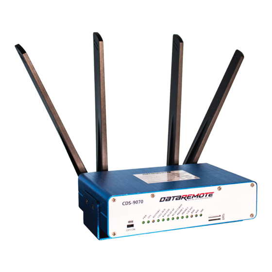
- Page 1 POTS in a BOX CDS9070 LTE VoIP Dual Band Wi-Fi Router / ATA User Manual V1.0...
-
Page 2: Table Of Contents
Table of Contents Preface .............................................. 6 LED Indicators and Connectors ......................................7 LED Indicators ........................................7 DC ..............................................9 Connector for a power adapter ....................................... 9 WAN ..............................................9 Connector for accessing the Internet ....................................9 LAN 1/2/3/4 ............................................. 9 Connectors for local networked devices.................................. - Page 3 4.7.2 Encryption ....................................... 33 Setting up WAN Failover ....................................35 4.8.1 WAN Failover List ....................................35 4.8.2 Connection Manager Wan Detection Probe ............................37 Register ........................................... 38 4.9.1 Get the Accounts ..................................... 38 4.9.2 Connections ......................................38 4.9.3 View the Register Status ..................................39 4.10 Make Call ........................................
- Page 4 5.4.1 Basic ........................................75 5.4.2 Security ........................................78 5.4.3 WPS ........................................80 5.4.4 Station list ....................................... 82 5.4.5 Client ........................................82 Phone ..........................................84 5.5.1 VoIP QoS ......................................... 84 5.5.2 Dial Plan........................................84 5.5.3 Blacklist ........................................86 5.5.4 Call Log ........................................87 SIP Account........................................
- Page 5 5.10.1 Logout ........................................114 5.10.2 Reboot ........................................114 Troubleshooting Guide ......................................... 115 Setting up your PC to get an IP automatically .............................. 115 Cannot connect to the Management Portal ..............................117 Forgotten Password ....................................... 117 Statement ............................................118...
-
Page 6: Preface
Preface Thank you for choosing CDS9070 wireless router with VoIP. This product will allow you to make ATA calls using your broadband connection, and it will also provide Wi-Fi router function. This manual provides basic information on how to install and connect your CDS9070 wireless router with VoIP to the Internet. It also includes features and functions of LTE connection, wireless router with VoIP components, and how to use it correctly. -
Page 7: Led Indicators And Connectors
LED Indicators and Connectors Before you use your high-speed router, please get acquainted with the LED indicators and connectors first. LED Indicators Front Panel Status Explanation The router is powered on (External On (GREEN) Power) and running normally. The router is powered on (Internal On Blinking (GREEN) Power - BAT) and running normally. - Page 8 Non active for Key registration WLAN On (GREEN) Wireless Client Connected Client On Blinking (GREEN) Wireless traffic (Data) The Wireless Client is powered off or WLAN not connected On (GREEN) Wireless AP ready On Blinking (GREEN) Wireless traffic (Data) The Wireless AP is powered off On (GREEN) Connected (Registered) On Blinking (GREEN)
-
Page 9: Connector For A Power Adapter
Rear Panel Interface Description Connector for a power adapter Connector for accessing the Internet LAN 1/2/3/4 Connectors for local networked devices... -
Page 10: Hardware Installation
Hardware Installation Before starting to configure the router, you must ensure your devices are connected correctly. Step 1. Connect the Line port to the analog Jack (Phone/Alarm Panel) with an RJ-11 Phone cable. Step 2. Connect the WAN port to a modem, switch, router, or Internet with an RJ-45 Ethernet cable. Step 3. -
Page 11: Interactive Voice Response
Interactive Voice Response Interactive Voice Menu Step 1. Pick up the phone and dial “ ” to start IVR. **** Step 2. Choose your desired options as dictated by the attendant with designated numbers 1-9. Step 3. If prompted to "Please enter password,” input your password followed by the “ ”... - Page 12 Notice: When using the Interactive Voice Menu, press the “ ” key to return to the main menu If any changes are made in the IP assignment mode, please reboot the CDS9070 to allow the settings to take effect ...
- Page 13 To input: D, E, F, d, e, f ‒ dial ‘3’ To input: G, H, I, g, h, I ‒ dial ‘4’ To input: J, K, L, j, k, l ‒ dial ‘5’ To input: M, N, O, m, n, o ‒ dial ‘6’ ...
-
Page 14: Configuring Basic Settings
Configuring Basic Settings Administrator Management This chapter explains how to setup a password for an administrator user and how to adjust settings for accessing the Internet successfully. The CDS9070 supports two-tier management: administrator and user. Login to the administrator tier with the credentials, “driadmin/DRIAdmin1” (Username/Password) and click the Login button. -
Page 15: Accessing Management Portal
Accessing Management Portal 4.2.1 From LAN port 1. Make sure your PC is connected to the router’s LAN port correctly. Notice: You may either set up your computer to get an IP dynamically from the router or set up the IP address of the computer to have the same subnet as the default subnet of the router 192.168.1.1/24. - Page 16 Notice: If you fail to access the web configuration, please see the Troubleshooting Guide for potential solutions. 4. The web configuration page will timeout after 30 minutes of inactivity. Notice: You can change this setting by navigating to: The “Administration” Tab → the “Management” Sub-Tab → the “Web Access” Section → “Web Idle Timeout(0 – 60min).” ✧...
-
Page 17: Cds-9070 Management Portal Layout
CDS-9070 Management Portal Layout Name Description Click the navigation bar, many Navigation sub-navigation bars will appear in the place 2 Click the sub-navigation bar to Title choose the corresponding configuration page Parameter Individual value fields Any time a change is made the user should press this button to confirm the changes... - Page 18 After pressing this button, and depending on the changes made, a red notice will appear requesting a reboot for the changes to take effect Press this button to cancel any changes Press this button to reboot the router...
-
Page 19: Setting Up The Time Zone
Setting up the Time Zone Navigate to the “Administration” Tab → the “Management” Sub-Tab → the “NTP Settings” Section, specify the NTP server, and set the update interval in NTP synchronization. -
Page 20: Setting Up The Internet/Wan Connection
Setting up the Internet/WAN Connection Navigate to the “Network” Tab → the “WAN” Sub-Tab → the “WAN” Section → “WAN IP Mode.” Select the appropriate IP Mode according to the information from your ISP. There are four modes provided: Static, DHCP, PPPoE, and Bridge. - Page 21 Choose from eight different Service types: “Voice,” “Management,” “Internet,” “Management_Internet,” Service “Management_Voice,” “Voice_Internet,” “Management_Voice_Internet,” and “Other” The mode used to obtain an IP WAN IP address. Choose between “Static,” Mode “DHCP,” “PPPoE,” and “Bridge” Choose “Disable,” “Enable,” or “Trunk.” If “Enable” or “Trunk” VLAN are selected, you should set your Mode...
- Page 22 Set the DNS Mode to Auto or Manual: DNS Mode If manual, you should fill-in the desired primary DNS address and Secondary DNS address...
-
Page 23: Dhcp
4.5.1 DHCP It is not necessary for you to type any IP address manually with this option. Simply choose this type and the system will obtain the IP address automatically from the DHCP server. Choose from eight different Service types: “Voice,”... - Page 24 Choose “Disable,” “Enable,” or “Trunk.” If “Enable” or “Trunk” VLAN are selected, you should set your VLAN ID to any number 1-4094 Mode and select any number 0-7 for 802.1p Set the DNS Mode to Auto or Manual: DNS Mode If manual, you should fill-in the desired primary DNS address and Secondary DNS address...
-
Page 25: Pppoe
4.5.2 PPPoE PPPoE stands for Point-to-Point Protocol over Ethernet. It relies on two widely accepted standards: PPP and Ethernet. It connects users through an Ethernet to the Internet with a common broadband medium such as a single DSL line, wireless device, or cable modem. All the users over the Ethernet can share a common connection. - Page 26 Assign a specific, valid PPPoE username provided by Account your ISP PPPoE Assign a valid password Password provided by your ISP Confirm Input the password again Password Input the destination of Service the PPPoE server, leave Name empty for auto detect...
- Page 27 Select “Keep Alive”, “On Operation Demand” or “Manual” Mode Keep Alive Redial The interval time for Period(0- redialing 3600s) Demand The interval time for idle Idle timeout Time(0- 60m)
-
Page 28: Setting Up The Internet/Lte Connection
Setting up the Internet/LTE Connection 4.6.1 Select “Disable,” “Auto Connect,” or “Always Modem Connect” Enable 4G connection type ,auto Connection or manual Type Access Point Name (Supplied by LTE Carrier) Dial LTE connection dial Number number Username Authorization username Password Authorization password... - Page 29 Internet Here you can choose 3G, 4G, or auto mode Connection Lock Cell Lock cell function Status PIN code bind status SIM bind Input the SIM bind code Limit of operation error The remaining time messages, should number of be less than or equal to unlock When LTE has connected successfully, return to the Status page to check the link status and the IP address obtained from your ISP.
-
Page 30: Setting Up The Wireless Connection
Setting up the Wireless Connection To set up the wireless connection, please read the following steps. 4.7.1 Enable Wireless and Setting SSID Open Wireless 2.4GHz or 5GHz / Basic webpage as shown below Radio On/Off Select to enable or disable wireless Wireless Connection Select Access Point or Client... - Page 31 Broadcast Broadcast or hide the SSID (SSID) Prevents a wireless client from AP Isolation communicating with other wireless clients. Other clients outside the Access Point MBSSID AP cannot access the clients under this Isolation Access Point A group of wireless workstations and a wireless local area network access point form a basic service set (BSS), each BSSID...
- Page 32 with the legacy 802.11a/g, the rest of the packet has a new format Green Field: In this mode, high throughput packets are transmitted without a legacy compatible part Channel 20 Channel Width = 20 MHz Bandwidth 20/40 Channel Width = 20/40 MHz Extension Choose the extension channel Channel(5G...
-
Page 33: Encryption
4.7.2 Encryption Open Wireless 2.4GHz or 5GHz / Wireless Security webpage to set the encryption. SSID Choose one SSID from the drop-down WAP-PSK/WAP2-PSK/WAPPSKWAP2PSK list Choice Choose an encryption method from the drop-down list, if disabled, wireless Security transmissions to and from your wireless Mode network can be easily intercepted and interpreted by unauthorized users... - Page 34 Wireless Connection Security Password Pass Phrase (min. 8 characters) The amount of time before the group Renewal key used for broadcast and multicast data is changed Interval Select one of the four WEP keys, the Default Key key settings on the client network card also need to correspond with this Set the WEP key: a 64-bit, Hex key will be 10 characters long, and a 64-bit,...
-
Page 35: Setting Up Wan Failover
Setting up WAN Failover 4.8.1 WAN Failover List WAN Failover works With the Wan, LTE, And Wi-Fi bands to assure that you maintain Internet connectivity if a loss of connection occurs. If one of your ISP links goes down, WAN Failover will automatically route all traffic over the other WAN interface(s) until service is restored. - Page 36 The CDS9070 allows failover of the default route to WAN interfaces. You can rank each interface in order of preferred usage for the default route. The default route will always be set to the highest- priority connected interface. The assignment changes as interfaces connect or disconnect from the current network.
-
Page 37: Connection Manager Wan Detection Probe
4.8.2 Connection Manager Wan Detection Probe Enabling this function will cause the WAN Failover to be based on ping result, disabling this function will Enable cause the WAN Failover to be based on each interface’s physical connection status Interval time for detecting Detect Interval WAN connection... -
Page 38: Register
4.9 Register 4.9.1 Get the Accounts The CDS9070 has 2 Analog phone ports that can be used to make SIP calls, but you should get the SIP account from your administrator or provider before registering. 4.9.2 Connections Connect your CDS9070 to the Internet properly. -
Page 39: View The Register Status
4.9.3 View the Register Status To view the status, please open the Status webpage and view the FXS Account registration status. If your FXS Account registration status resembles the following picture below, your CDS9070 has registered normally and you are ready to make calls. -
Page 40: Make Call
4.10 Make Call 4.10.1 Calling phone or extension numbers To make a phone or extension number call: a) Both ATA and the other VoIP device (i.e. another ATA or other SIP product) have public IP addresses - or - b) Both ATA and the other VoIP device (i.e. another ATA or other SIP product) are on the same LAN using private or public IP addresses - or - c) Both ATA and the other VoIP device (i.e. -
Page 41: Direct Ip Calls
4.10.2 Direct IP calls Direct IP calling allows two phones (an ATA with an analog phone and another VoIP Device) to talk to each other without a SIP proxy. VoIP calls can be made between two phones if: a) Both ATA and the other VoIP device (i.e. another ATA or other SIP product) have public IP addresses - or - b) Both ATA and the other VoIP device (i.e. -
Page 42: Call Hold
4.10.3 Call Hold While in a conversation, dialing “ 77” will put the remote party on hold. You will then hear dial tone while the remote party will hear hold tone. Dialing “ 77” again will reverse the hold state and resume the bi-directional media. 4.10.4 Blind Transfer While in a conversation, Party A wants to Blind Transfer Party B to Party C: Step 1. -
Page 43: Conference
Step 2. Party A dials “ 78” to transfer Party C to Party B. Step 3. If the transfer doesn’t succeed, then Party A and Party B will be returned to their original conversation. 4.10.6 Conference While in a conversation, Party A and Party B want to add Party C to a Conference: Step 1. -
Page 44: Management Portal
5 Management Portal This chapter will guide users through admin level configuration. 5.1 Login Step 1. Connect the LAN port of the CDS-9070 to your PC Step 2. Open a web browser on your PC and type in http://192.168.1.1. You will be prompted for username and password. - Page 45 After successfully logging-in, the webpage will show the basic information about your CDS9070 such as the current Firmware Version, received signal strength indicator (RSSI), WAN IP, DNS server IP, WAN port connection mode, LAN port connection, wireless broadcast status, wireless channel, and wireless connection mode...
-
Page 46: Status
5.2 Status... - Page 47 The picture above depicts the CDS9070’s Status webpage. This Status / Basic webpage shows the status information about product information, network and system. It also shows other basic information about your CDS-9070 such as product name, serial number, MAC address, hardware version, and firmware version.
-
Page 48: Network
5.3 Network You can configuration the WAN port, LAN port, DDNS, Multi WAN, DMZ, MAC Clone, Port Forward and so on in these two bars. 5.3.1 WAN This page allows you to set WAN configuration with different modes. Use the Connection Type drop-down list to choose a WAN mode and then the corresponding options will be displayed. - Page 49 Choose from eight different Service types: “Voice,” “Management,” “Internet,” “Management_Internet,” Service “Management_Voice,” “Voice_Internet,” “Management_Voice_Internet,” and “Other” The mode used to obtain an IP WAN IP address. Choose between “Static,” Mode “DHCP,” “PPPoE,” and “Bridge” Choose “Disable,” “Enable,” or “Trunk.” If “Enable” or “Trunk” VLAN are selected, you should set your Mode...
- Page 50 Set the DNS Mode to “Auto” or “Manual”: DNS Mode If manual, you should fill-in the desired primary DNS address and Secondary DNS address...
- Page 51 DHCP: IP address will be automatically set for you with this option selected. Simply choose DHCP from the drop- down list and the system will obtain an IP address automatically from the DHCP server. Choose from eight different Service types: “Voice,”...
- Page 52 are selected, you should set your VLAN ID to any number 1-4094 and select any number 0-7 for 802.1p Set the DNS Mode to Auto or Manual: DNS Mode If manual, you should fill-in the desired primary DNS address and Secondary DNS address PPPoE: PPPoE stands for Point-to-Point Protocol over Ethernet.
- Page 53 PPPoE is used for most of DSL modem users. All local users can share one PPPoE connection for accessing the Internet. Your service provider will provide you information about user name, password, and authentication mode. Choose from eight different Service types: “Voice,”...
- Page 54 Choose “Disable,” “Enable,” or “Trunk.” If “Enable” or “Trunk” are selected, you VLAN should set your VLAN ID to Mode any number 1-4094 and select any number 0-7 for 802.1p Set the DNS Mode to Auto or Manual: If manual, you should fill-in DNS Mode the desired primary DNS address and Secondary DNS...
- Page 55 Confirm Input the password again Password Input the destination of the Service PPPoE server, leave empty Name for auto detect Select “Keep Alive”, “On Operation Demand” or “Manual” Mode Keep Alive Redial The interval time for Period(0- redialing 3600s) Demand The interval time for idle Idle timeout...
-
Page 56: Lan
5.3.2 LAN LAN Port: The most generic function of router is NAT. NAT translates the packets from public IP addresses to local IP addresses, forwarding the right packets to the right host. Local IP Type in the local IP address for connecting to a local private network Address Local Subnet... - Page 57 “Manual” from the drop-down list to manually enter the DNS Server addresses Client Lease Set the lease time for the specified address Time DHCP Client Check which LAN devices are currently leasing IP addresses List DHCP Static Specify DHCP addresses to reserve Allotment Enable to use a device as a DNS DNS Proxy...
-
Page 58: Vpn/L2Tp
5.3.3 VPN/L2TP Enable PPTP or VPN Enable L2TP VPN Client VPN server IP Initial Service address The account for User Name authentication The password for Password authentication The remote VPN As virtual IP as Default Route default gateway. MPPE Stateless Stateful(PPTP encryption provides a lower... - Page 59 level of performance, but will be more reliable in a noisy network environment. Enable MPPE (Microsoft Point- to-Point Require Encryption). It’s MPPE(PPTP a protocol for Only) encrypting data across PPP and VPN links. L2TP Tunnel Enter L2TP Name Tunnel Name. Enter L2TP L2TP Tunnel tunnel password...
- Page 60 L2TP Server L2TP Server Select to enable L2TP server. Enable Local IP Set the IP address of L2TP server. Address Pool Start Set the IP pool start IP address which Address will assign to the L2TP clients. Pool End Set the IP pool end IP address which Address will assign to the L2TP clients.
- Page 61 Set the username which will assign to User Name L2TP client. Set the password which will assign to Password L2TP client.
- Page 62 IPsec Connection IPsec The connection status of Connection List the IPsec VPN IPsec Select to specify VPN Connection Connection The name of the IPsec Name Select to enable or IPsec Enable disable IPsec VPN Select the interface for Interface encryption IPsec The connection type of Networking...
- Page 63 the IPsec VPN Select the local ID type Local ID Type for the IKE negotiation Local IP address or Local WANs IP domain name for the Address/FQDN IKE negotiation Select the remote ID Remote ID type for the IKE Type negotiation Remote WANs The address of remote...
- Page 64 Subnet Mask Length The policy protocol for Policy Protocol encryption Encapsulated Select the security Mode protocols Enable NAT Traversal for IPsec. This item NAT Enable must be enabled when router under NAT environment Select from “Main” and “aggressive” for the IKE Mode negotiation mode in phase 1...
- Page 65 Select Integrity Integrity Algorithm to be used in Algorithm IKE negotiation Select Diffie-Hellman Diffie-Hellman Group to be used in key (DH) Group negotiation phase 1 Set the lifetime in IKE SA Lifetime of Phase 1 negotiation Set the interval after which DPD is triggered DPD Time if no IPsec protected...
-
Page 66: Dmz/Port Forward
Select Integrity Integrity Algorithm to be used in Algorithm IPsec SA negotiation SA Lifetime of Set the lifetime in IPsec SA negotiation Phase 2 Enable or disable PFS: (Perfect Forward Secrecy)PFS will ensure the same key will not be generated again 5.3.4 DMZ/Port Forward DMZ Enable Enable or disable DMZ... - Page 67 Get the current PC’s IP address Get Current automatically, this IP address would be used as the DMZ PC IP host Port Forward Port Forwarding Assign a meaningful name Comment for port forwarding IP Address The IP address for LAN The port range for LAN Port Range host, from 1 to 65535...
- Page 68 Servers Assign a meaningful name Comment to the virtual server The IP address of the system on your internal IP Address network that will provide the virtual service The port that will be Public Port accessed from the Internet. The port that will be used Private Port on your internal network.
-
Page 69: Ddns
5.3.5 DDNS Select the DDNS Dynamic service which you have established an Provider account with Enter account that Account DDNS server provided Enter password that Password DDNS server provided Enter the DDNS DDNS Domain name or IP address Show current status Status of DDNS... -
Page 70: Qos
5.3.6 QoS Select to enable QoS function QoS Enable Upstream Prescribe uplink speed of router. Downstream Prescribe downlink speed of router. Set server name of the service that you Name want to set it with QoS Control. Enter source IP address of the user (for Source IP example, PC) who you want to set it with Address... - Page 71 Physical Port Select from WAN/LAN set the Differentiated Services Code DSCP Point (DSCP) values in Quality of Service (QoS) 802.1p is an IEEE standard that describes mechanisms to prioritize traffic and 802.1p perform dynamic multicast filtering. When configuring a VLAN tag-based QoS policy map, the router applies the VLAN ID policy to one Ethernet port and only to...
-
Page 72: Mac Clone
effort (BE), and background (BK) Drop Select to Drop or not drop the packet Rate Limit Limit the speed of this rule 5.3.7 MAC Clone Some ISPs will require you to register your MAC address. If you do not wish to re-register your MAC address, you can have the router clone the MAC address that is registered with your ISP. - Page 73 The MAC address for Address clone clone the currently PC Current MAC address to router’s Internet port automatically...
-
Page 74: Routing
5.3.8 Routing The IP address of packets Destination that will take this route Select the Host or Host/Net Networking Specifies the next hop to Gateway be taken if this route is used. Specifies the interface LAN/ INTERNET/ Interface VOICE/ TR069/ VPN Set comment of this Comment routing... -
Page 75: Wireless
5.4 Wireless 5.4.1 Basic Radio On/Off Select to enable or disable wireless Wireless Connection Select Access Point or Client Mode Choose a network mode from the drop- Network Mode down list Multiple SSSD Set and name multiple SSID’s Broadcast Broadcast or hide the SSID (SSID) Prevents a wireless client from communicating with other wireless... - Page 76 Access Point A group of wireless workstations and a wireless local area network access point form a basic service set (BSS), each BSSID computer in the BSS must be configured with the same BSSID Frequency Choose a channel frequency The HT (High Throughput) Physical HT Physical mode settings allow for control of the Mode...
- Page 77 20 Channel Width = 20 MHz Channel Bandwidth 20/40 Channel Width = 20/40 MHz Extension Choose the extension channel Channel(5G frequency Hz Only) With IEEE 802.11ac standard, very- high-throughput packets can be Option(5GHz configured to operate on the 5 GHz Only) frequency band 20/40 Channel Width = 20/40 MHz...
-
Page 78: Security
5.4.2 Security Open 2.4G (5G)/Security webpage to set the encryption of routers. Choose one SSID from the drop-down SSID WAP-PSK/WAP2-PSK/WAPPSKWAP2PSK Choice list Choose an encryption method from the drop-down list, if disabled, wireless Security transmissions to and from your wireless Mode network can be easily intercepted and interpreted by unauthorized users... - Page 79 Wireless Connection Security Password Pass Phrase (min. 8 characters) The amount of time before the group Renewal key used for broadcast and multicast data is changed Interval Select one of the four WEP keys, the Default Key key settings on the client network card also need to correspond with this Set the WEP key: a 64-bit, Hex key will be 10 characters long, and a 64-bit,...
-
Page 80: Wps
5.4.3 WPS WPS (Wi-Fi Protected Setup) provides easy procedure to make network connection between wireless station and wireless access point (vigor router) with the encryption of WPA and WPA2. It is the simplest way to build connection between wireless network clients and vigor router. Users do not need to select any encryption mode and type any long encryption passphrase to setup a wireless client every time. - Page 81 and then click Apply. PBC: PBC mode There are two ways to start, you can directly press the PBC button on the hardware, or select to PBC mode, and then click Apply There are three WPS states: WSC: Idle state is idle WSC: Start WSC Process Status is to WPS Status start sending messages...
-
Page 82: Station List
5.4.4 Station list You could monitor stations which associated to this AP here 5.4.5 Client Enable Wi-Fi Client would be one option for WAN Failover, select as the default route. Current Wi-Fi Client Connection Status connect status... - Page 83 Select one SSID and press the button, Connect enter the password for the SSID Refresh the SSID Refresh scan result Add one new/hidden SSID manually...
-
Page 84: Phone
5.5 Phone 5.5.1 VoIP QoS QoS services can improve the quality of voice applications. The default value SIP QoS(0-63) is 46, and the range of values can be set from 0 to 63. Once Multi-WAN port is enabled, select the corresponding voice PPPoE RTP QoS(0-63) server VID, the devices under the same VLAN can transmit voice data. - Page 85 Fill in the expression of digital map, Digital Map please refer to the digital map syntax. Select the match action of the digital map, Deny means the device will reject the matching number dialing, and Dial Action Out means the device can dial out the matching number...
-
Page 86: Blacklist
5.5.3 Blacklist You can upload or download the phone book, blacklist... -
Page 87: Call Log
5.5.4 Call Log On this page, users can view replay lists (outgoing calls), received calls, and missed calls. -
Page 88: Sip Account
5.6 SIP Account 5.6.1 FXS1/2 SIP Account Select to enable or disable Line Enable line Outgoing Select to enable or disable Call without this function Registration Display The display name of this SIP number Name The phone number provided Phone Number by SIP server The account provided by... -
Page 89: Fxs1/2 Audio Configuration
5.6.2 FXS1/2 Audio Configuration Select the appropriate Audio Codec Type encoding Select from 5.3kbps or G.723 Coding Speed 6.3kbps Set the RTP packetization period. Packet Cycle(MS) The default configuration is 20ms Silence Supp Mute enable Echo Cancellation is Echo Cancel enabled by default Used to automatically adjust the speech level... - Page 90 Select from local or Codec Priority remote Select to enable or Packet Cycle Follows Remote SDP disable Select from T.30/ FAX Mode T.38/ Bypass Select from Bypass Attribute Value fax/modem or X- fax/X-modem Select to enable or T.38 CNG Detect Enable disable T.38 CED Detect...
-
Page 91: Fxs1/2 Supplementary Service Subscription
5.6.3 FXS1/2 Supplementary Service Subscription Call Select to enable or disable Waiting Fill in the hotline number. After the subscriber is set up successfully, the hotline number Hot Line will be automatically dialed immediately after off-hook Enable WMI (Message Waiting Indication), enable this function Enable if you want to use voicemail... - Page 92 default is disable Pre-set the phone number for Speed Dial Fast call...
-
Page 93: Security
5.7 Security 5.7.1 Filtering Setting Select to enable Filtering or disable Select from Drop Default Policy or Accept Select from LAN Interface or WAN Fill MAC address for address Filtering control Fill Destination Dest IP IP address for Address Filtering control... - Page 94 Fill source IP Source IP address for Address Filtering control Select from TCP/ Protocol UDP /ICMP Fill Destination Dest. Port port range for Range Filtering control Fill source port Src Port range for Range Filtering control Select from Action Accept or Drop Fill the comment for this filtering Comment...
-
Page 95: Content Filtering
5.7.2 Content Filtering Select to enable or Filtering disable Select from Default Drop or Policy Accept Select the local file for Local File upload Current Existing URL Webs filtering rules (blacklist) Filters Add a Add a URL filtering rule Filter... - Page 96 Fill the URL for webs filtering Current Existing Website keywords Host (blacklist) Filters Add a Add a Host (keyword) keyword rule Filter Fill the Keyword keyword for filtering...
-
Page 97: Application
Application 5.8.1 Advance Nat In this page, you can choose to enable / disable FTP, SIP, H323, PPTP, L2TP, IPsec services. -
Page 98: Upnp
5.8.2 UPnP UPnP (Universal Plug and Play) supports null-setting for networking, can automatically find a variety of networked devices. When UPnP is enabled, UPnP- enabled devices are allowed to dynamically access the network, obtain IP addresses, and transmit performance information. If you have DHCP and DNS servers on your network, you can automatically obtain DHCP and DNS services. -
Page 99: Igmp
5.8.3 IGMP Multicast has the function of sending the same data to multiple devices. An IP host uses the IGMP (Internet Group Management Protocol) to report multicast group memberships to send data to neighboring routers, and the multicast router uses IGMP to discover which hosts belong to the same multicast group. -
Page 100: Administration
5.9 Administration 5.9.1 Management Save Configuration File Select the local file for Local File configuration Use this option to restore previously saved router Upload configuration settings. This option allows you to export and then save the router's configuration to a file on your computer. - Page 101 Administrator Settings New user name for New User Name management Type the password for Password user Type the same password Confirm Password again Setup the language for operation, select from Language English or Spanish The auto refresh interval Refresh Interval for LTE status Management Select to enable or disable...
- Page 102 Enter the HTTP port Local Web number for accessing from Port local side Enter the HTTP port Web Port number for accessing from remote side Web Idle Timeout for web idle Timeout activity (0 -60min) Allow the host with Allowed Remote IP specified IP address to (IP1;...
- Page 103 Time/Date Settings Select this option if you want to synchronize the NTP Enable router's clock to a Network Time Server over the Internet. Obtain NTP Option 42 Server via DHCP Server Displays the time currently Current Time maintained by the router Synchronize Sync with host with your...
- Page 104 current host's system time Select your local NTP Settings time zone from drop-down list Type the primary Primary NTP Network Time Server Server for synchronization Type the secondary Secondary NTP Network Time Server Server for synchronization Interval time for synchronization (1 -1440min) synchronization...
-
Page 105: Firmware Upgrade
Reset to Factory Default This option restores all configuration settings back to the settings that were in effect at the time the router was shipped from the factory. Any settings that have not been saved will be lost. 5.9.2 Firmware Upgrade Once you have a firmware update on your computer, use this option to browse for the file and then upload the... -
Page 106: Scheduled Tasks
5.9.3 Scheduled Tasks Scheduled Select to enable or Wi-Fi disable Enable Choose the specified SSID SSID for scheduled Wi- Select the Schedule Scheduled Mode mode for cycle time Wi-Fi Setup the working time Work for Wi-Fi broadcast Time Select to enable or Scheduled Reboot disable... - Page 107 Select to enable or Scheduled PPPOE disable Select the Schedule Scheduled Mode mode for cycle time Setup the Pope Time connection timing...
-
Page 108: Provision
5.9.4 Provision Please refer to the provision user manual to test provision. Provision Select to enable or disable Enable Enable or disable DIV378 Resin On Reset Resin after rebooting Setup the maximum delay Resin Random for request Delay(sec) synchronization If the last resynchronization is unsuccessful, after the Resin... - Page 109 If it is time to re-sync, but the device is busy, in this case, the device will wait for some time, the longest Forced Resin is "forced Delay(sec) resynchronization delay", the default is 14400s, time after the device will be forced to re-sync.
- Page 110 Specifies the startup file Option 67 name Config File Configure the file name Name User Agent The name of user agent The URL of the configuration file Note that the specified file Profile Rule path is relative to the root directory of the TFTP server Upgrade...
-
Page 111: Tr069
5.9.5 TR069 Select to enable TR069 Enable or disable Select to enable CWMP or disable The URL of ACS agent The user name User Name of ACS agent The password Password of ACS agent... - Page 112 Select to enable or disable the Periodic Inform periodic Enable notification function is Setup periodic Periodic Inform Notification Interval Interval User name for TR069 server User Name connected to Password for TR069 server Password connected to...
-
Page 113: System Log
5.10 System Log If you enable the system log in Status/syslog webpage, you can view the system log in this webpage. -
Page 114: Logout
5.10.1 Logout Press the logout button to logout, and then the login window will appear. 5.10.2 Reboot Press the Reboot button to reboot CDS9070. -
Page 115: Troubleshooting Guide
6 Troubleshooting Guide 6.1 Setting up your PC to get an IP automatically Following are the process of setting your PC gets IP automatically Step 1. Click the “begin ” Step 2. Select “control panel”, then double click “network connections” in the “control panel” Right clicks the “network connection”... - Page 116 Picture 2 Picture 1...
-
Page 117: Cannot Connect To The Management Portal
6.2 Cannot connect to the Management Portal Solution: Check if the Ethernet cable is properly connected, then Check if the URL is Written Correctly, the format of URL is: http:// the IP address. Check if the version of IE is IE8, or use other browser such as Firefox or Mozilla, then Contact your administrator, supplier, or ITSP for more information or assistance. -
Page 118: Statement
7 Statement FCC Radiation Exposure Statement Data Remote Incorporated. Declares that this device is in compliance with the essential requirements and other relevant provisions of Directive 1999/5/EC. This equipment has been tested and found to comply with the limits for a Class B digital device, pursuant to part 15 of the FCC rules. - Page 119 -Connect the equipment into an outlet on a circuit different from that to which the receiver is Connected. -Consult the dealer or an experienced radio/TV technician for help. To assure continued compliance, any changes or modifications not expressly approved by the party Responsible for compliance could void the user’s authority to operate this equipment.
- Page 120 Undesired operation. This equipment should be installed and operated with minimum distance 20cm between the radiator And your body.
Need help?
Do you have a question about the DataRemote POTS in a BOX CDS9070 and is the answer not in the manual?
Questions and answers