
Related Manuals for DeLonghi CLIMAVENETA HED HCAT 0011 SE


Summary of Contents for DeLonghi CLIMAVENETA HED HCAT 0011 SE
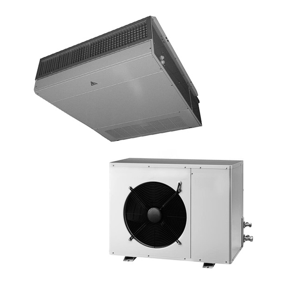
- Page 1 INSTALLATION AND SERVICE MANUAL Free Cooling direct expansion terminal units HED-HCAT SE 0011-0021-0031 0041-0051-0056 -0061 FREE COOLING Standard & Silented version...
-
Page 3: Outdoor Unit
INDEX INDOOR UNIT OUTDOOR UNIT General warnings Identification Fundamental safety rules Receiving and handling the product Standard unit description HCAT Identification Receiving and handling the product Dimensional drawings Installation Description of standard unit Dimensional drawings Refrigerant pipe connection Installation Sizing of refrigerant pipes Electrical connection Functional distances Refrigerant pipe connection... -
Page 4: General Warnings
GENERAL WARNINGS HED SE FC terminal units are the internal units undamaged. of a ”split” two section system. Combined with a If damage, missing components or consignment er- HCAT SE condenser unit, they form a combined air rors are noted, indicate this on the delivery note. A conditioning and heating system. - Page 5 IDENTIFICATION HED SE direct expansion terminals can be identified by the: De' Longhi S.p.a. - 31100 Treviso / Italia Via L.Seitz, 47 - tel. 04224131 fax 0422413659 MODELLO: TENSIONE: CODICE: Packaging label Giving the data identifying the product. Rating plate POTENZA FRIGORIFERA ------------------- Giving the technical and performance data of the unit.
-
Page 6: Description Of Standard Unit
DESCRIPTION OF STANDARD UNIT STRUCTURE HAETING ELEMENT MODULE Structure in hot-galvanised steel panelling, com- The heating element module consists of a heating element plete with couplings for connection to ducting and installed on a rack and placed inside the unit.The power is gravity drain condensate pan. -
Page 7: Dimensional Drawings
DIMENSIONAL DRAWINGS SIZE 0011-0021-0031 2 200 1499 226 41 SIZE 0041-0051-0056-0061 1524 1107 1054 Size Fittings Weight Ø1 Ø2 (kg) 0011-0021-0031 15,8mm-5/8” 9,52mm-3/8” 19,05mm-3/4” 12,3mm-1/2” 0041-0051-0061 HED-HCAT SE FREE COOLING ENGLISH... -
Page 8: Choice Of Installation Site
INSTALLATION CHOICE OF INSTALLATION SITE POSITIONING Before installing the unit, agree the site where it will be in- Before handling the unit, check the capacity of the lift stalled with the customer, taking the following points into equipment used, respecting the instructions on the packag- consideration: ing. -
Page 9: Refrigerant Pipe Connection
REFRIGERANT PIPE CONNECTION REFRIGERANT PIPES LIQUID PIPE Sizing of the refrigerant pipes connecting the external con- To connect, proceed as follows: denser units and internal evaporator units is vital to guar- 1. Connect the pipe to the liquid union coupling using antee correct operation. -
Page 10: Refrigerant Circuit
REFRIGERANT CIRCUIT Flared gas pipe connection Flared liquid pipe connection Expansion device Finned coil POWER CONNECTIONS The direct expansion terminals leave the factory complete- tral and earth conductors. ly wired and ready for connection to the mains electricity The power line should be fitted upstream with a supply, accessories and the receiver. -
Page 11: General Technical Data
ELECTRIC HEAT ELEMENT POSITIONING 0011-0021-0031 0041-0051-0061 Electric heat element kW GENERAL TECHNICAL DATA 0011-0021 003 1 0041-0051 0056-0061 Total Cooling capacity 4,7-6,0 9,0-11 13,8-15,2 Sensible Cooling Capacity 4,4-5,5 8,7-10,6 13,4-14,0 Unit power supply V-Ph-Hz 230-1-50 400-3-50 400-3-50 Compressor absorbed power 1,20-1,60 3,3-4,4 Evaporator air flow rate... -
Page 12: Routine Maintenance
ROUTINE MAINTENANCE IMPORTANT: CHECKING THE STATE OF AIR FILTERS - Power to the unit must be disconnected before carrying Depending on the environment in which the internal unit is out maintenance or cleaning. installed, the air filters must be cleaned periodically. - At the beginning of the season you are recommended to In particularly dusty atmospheres, the air filters should be contact qualified personnel for the seasonal start-up. -
Page 13: Electrical Panel Layout
ELECTRICAL PANEL LAYOUT HED-HCAT SE FREE COOLING ENGLISH... - Page 14 MULTIFILAR CIRCUIT HED HCAT 0011-0021-0031 HED-HCAT SE FREE COOLING ENGLISH...
- Page 15 HED HCAT 0041-0051-0061 HED-HCAT SE FREE COOLING ENGLISH...
-
Page 16: Receiving And Handling The Product
IDENTIFICATION The HCAT SE condenser units can be identified by the: Tampering with or De' Longhi S.p.a. - 31100 Treviso / Italia Via L.Seitz, 47 - tel. 04224131 fax 0422413659 MODELLO: the removal or ab- TENSIONE: CODICE: Packaging label sence of rating plates or Giving the data identifying the product. - Page 17 DESCRIPTION OF STANDARD UNIT The air-cooled condenser units with axial-flow fans opera- de air temperatures: continuous regulation of fan rota- te with R407C refrigerant and are suitable for outdoor in- tion speed via temperature transducer. stallation, for use with HED direct expansion terminals. The units conform to the essential requisites established in REFRIGERANT CIRCUIT EC directive 89/392.
- Page 18 DIMENSIONAL DRAWINGS Dimension 0011-0021-0031 0041-0051 -0056 0061 1250 91,5 91,5 91,5 Funtional distance Weights distribution HED-HCAT SE FREE COOLING ENGLISH...
-
Page 19: Refrigerant Connections
INSTALLATION CHOICE OF INSTALLATION SITE refrigerant and electrical components. If the site is exposed to Before installing the unit, agree the site where it will be instal- strong winds, fix the unit adequately using tie rods if neces- led with the customer, taking the following points into consi- sary. - Page 20 The HCAT SE units are pre-filled with a sufficient quantity of refrigerant for connection to the corresponding HED internal unit and for a maximum pipe length of 5m. PROCEDURE FOR CORRECT CONNECTION Intake/discharge piping 1. Insulate the piping adequately with anti-condensate every 6m and an air trap should be included before the “closed cell”...
- Page 21 SIZING OF REFRIGERANT PIPES SIZING CONNECTION PIPING IN RELATION TO EQUIVALENT DISTANCE Model 0011 0021 0031 0041-005 1 0061 Type of pipe0-10 m eq. Intake/discharge Ø mm Liquid Ø mm Type of pipe 10-20 m eq. Intake/discharge Ø mm Liquid Ø...
-
Page 22: Gas Connection
SIZE AND POSITION OF CONNECTIONS Size 0011-0021-0031 0041-0061 A (mm) 91,5 91,5 B (mm) C (mm) Gas connection (mm/inch) 15,9mm-5/8” 19,05mm-3/4” Liquid connection (mm/inch) 9,52mm-3/8” 12,8mm-1/2” Mod. 0011-0021-0031-0041-0061 MOD. 0021÷0041 LIQUID RUBINETTO CONNECTION LIQUIDO RUBINETTO CONNECTION CHECKING FOR LEAKS 1. Check that the valves on the external unit are 4. -
Page 23: Electrical Connections
ELECTRICAL CONNECTIONS The HCAT SE condenser units leave the factory fully wi- Voltage must be within a tolerance of ±10% of the rated red. Installation is limited to connection to the mains electri- power supply voltage for the unit (for three phase units, cal supply and connection of the remote (ON/OFF) switch, the unbalance between the phases must not exceed 3%). -
Page 24: Operating Limits
OPERATING LIMITS Cooling (°C) Inside temp. BS/BU °C. Outside temp. BS/BU °C. 32 / 23,5 50 / - 20 / 14,0 -20 / - BS: Bulbo secco BU: Bulbo umido SAFETY SETTINGS Opens Closes RESET (bar) (bar) High pressure switch 28,0 23,0 manual... -
Page 25: Activating And Deactivating The Unit
- Remove the door of the electrical panel, setting QS to OFF - Replace the inspection panel - Place the compressor thermal overload switch QM1 in the ON position - Place the main switch of the unit QF (outside of the unit) in the “ON”... - Page 26 REGULATION DIAGRAM Minimum Regulation of ON-OFF re- ON-OFF re- High tempe- Maximum temperature single air-con- gulation for gulation for rature signal operating alarm signal ditioner con- connection connection temperature and acknow- nection by mi- of 2nd air- of 2nd air- signal.
-
Page 27: Unit Controller
UNIT CONTROLLER Programming key Exit from menus Alarm warning Character display Scrolling selectors Enter key Unit controller Standard display The standard display page shows the main measurement values of the units: • Internal temperature T amb: • External temperature T est: •... -
Page 28: Status Screen
CONTROL AND DISPLAY PARAMETERS Click on the scrolling selectors to display the current sta- tus of the machine STATUS SCREEN _ _ _ _ _ _ _ _ _ _ /_ _ _/_ _ _ _ Temperature _ _ _ _ _ _ _ _ _ °C Humidity _ _ _ _ _ _ _ _ _ _ _ % Off Alarm U:00... - Page 29 Press the alarm warning key to display all the stored alarms displayed in the time period. Range H001-H999 press alarm key for record Select the password with the scrolling selectors to access the menu for setting the maintenance parameters. Factory value 123 Maintenance man Range 0+9999 password...
- Page 30 The mask Ad is used for manual activation of the digital outputs 6-7-8. Manual procedure Factory value Off. Digit. output 06 Range Off ÷ On Digit. output 07 Digit. output 07 The mask Ae is used for manual activation of the digital outputs 9-10-11.
- Page 31 The display page I2 shows the The display page I3 shows the gas condensation temperatu- status of the digital inputs 1-3 Digit. inputs 1-3 Analog inputs C1 low pressure Cond. temp.1 _ _ _°C Alarm C1 Cond. temp.2 _ _ _°C Heat.
- Page 32 MAINTENANCE MAN Click on the Esc key to return to the main display page. Printer To access the main menu, click on the programming key. Inputs/Outputs To enter the Setpoint menu, position on Setpoint with the Clock scrolling selectors and click on the enter key. Setpoint User MANUFACTURER...
- Page 33 The mask P5 is used to change the Freecool Humid Min and Max Humidity Set Point li- delta between the internal and ex- mits for Freecooling activation. Limit Enable :Yes/No ternal temperature in the Freecoo- ling mode. Freecooling DT _ _._ °C Min.
- Page 34 Used to change the maintenance man password. Select the required combination with the scrol- Maintenance man ling selectors and confirm with the enter key. user 0000 MAINTENANCE MAN Click on the Esc key to return to the main display page. Printer To access the main menu, click on the programming key.
- Page 35 The mask C3 is used to change (for pC020medium only) the number: of compressors Factory value 1 Compressors: Range 1 ÷ 2 Heat. el. No. of heating elements Factory value 1 Range 1 ÷ 2 Binar The display page C4 is used to enable the modulating delivery fan. Factory value Yes Range Yes ÷...
- Page 36 The mask Ca is used to: a) enable the pressure sensor 2 (for pC02medium only) Press. sensor Factory value Y Type Current Range Y ÷ N Min. thresh. 00.0bar b)set the value of the pressure sensor 2 signal (for pC02medium only). Max.
- Page 37 The mask G2 is used to set: Modulating Fan speed Screen Freecooling Modulating Fan Speed a) the percentage of the freecooling _ _ _._ % Min Speed _ _._ V minimum aperture proportional _ _ _._ % Max Speed _ _._ V band.
- Page 38 the display page T1 is used to set: the integration time for P+I temperature regulation Integr. time Factory value 600 Only P+1 0600 sec Range 0 ÷ 9999 Opening time Unit of measurement seconds Damper ____sec freecooling 3-point swing time Factory value 180 Range 0 ÷...
- Page 39 The display page T7 is used to set the freecooling off time due to high humidity limit Time off freec. Range 0÷ 999 For humid. Unit of measurement seconds limit _ _ _ min the display page T10 is used to set: Delay alarm Range 0 ÷...
- Page 40 Plan NETWORK SET -UP The representation to the side shows the necessary connection for setting up the pLAN network between the 2 units. UNIT 1 UNIT 2 Tx- Tx+ GND Tx- Tx+ GND 33 34 35 33 34 35 ADDRESSING AND MANAGEMENT OF CONNECTIONS BETWEEN BOARDS (pLAN) The pLAN network distinguishes a physical connection between pCO2 boards.The boards must be addressed for the network to operate correctly.
- Page 41 pLANSOFTWARE CONFIGURATION pLAN software configuration operations are carried out on the board configured as Master. Maintenance man Click on the Esc key to return to the main display page. Printer Inputs/Outputs Clock To access the main menu, click on the programming key. Setpoint To enter the Manufacturer menu, position on Manufactu- User...
- Page 42 Click on the ESC key to return to the MANUFACTURER CONFIGURATION menu. Parameters Carel EXV Driver To enter the PARAMETERS menu, position on PARAME- Delay times TERS with the scrolling selectors and click on the enter Initialization key. The mask Gb, which only activates in the plan mode, is used to define: a) number of units set in the stand-by mode Unit rotation Factory value: 0...
-
Page 43: Troubleshooting
TROUBLESHOOTING PROBLEM CAUSE REMEDY The fan does not activate Mains power failure Check presence of power Check fuse on terminal block On-off switch on “Off” Put to “On” Check room control Faulty room control Check fan motor Faulty fan Obstructed mesh filter Clean the filter Insufficient cooling Remove the obstacles... - Page 44 HED-HCAT SE FREE COOLING ENGLISH...
- Page 46 GRUPPO Via L.Seitz, 47 310100 Treviso Italia Tel. 0422 4131 - Telefax 0422 413659 www.delonghi.com...
Need help?
Do you have a question about the CLIMAVENETA HED HCAT 0011 SE and is the answer not in the manual?
Questions and answers