Dynojet Power Commander V Installation Instructions
2009-2015 suzuki gladius/svf650
Hide thumbs
Also See for Power Commander V:
- Installation instructions and owner's manuals (9 pages) ,
- Installation instructions manual (9 pages) ,
- Installation manual (9 pages)
Advertisement
2009-2015 Suzuki Gladius / SVF650
I n s t a l l a t i o n I n s t r u c t i o n s
PLEASE READ ALL DIRECTIONS BEFORE STARTING INSTALLATION
I20-013
www.powercommander.com
2191 Mendenhall Drive North Las Vegas, NV 89081 (800) 992-4993 www.powercommander.com
PARTS LIST
1
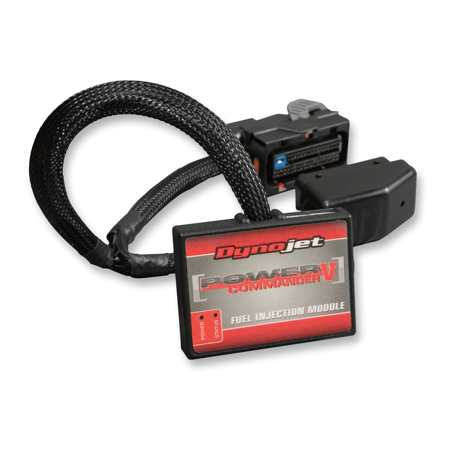
Power Commander
1
USB Cable
1
Installation Guide
2
Power Commander Decals
2
Dynojet Decals
2
Velcro strips
1
Alcohol swab
THE IGNITION MUST BE TURNED
OFF BEFORE INSTALLATION!
YOU CAN ALSO DOWNLOAD THE
POWER COMMANDER SOFTWARE AND
LATEST MAPS FROM OUR WEB SITE AT:
www.powercommander.com
2009-2015 Suzuki Gladius SVF650 - PCV - 1
Advertisement
Table of Contents

Related Manuals for Dynojet Power Commander V


Summary of Contents for Dynojet Power Commander V
- Page 1 Installation Guide 2009-2015 Suzuki Gladius / SVF650 Power Commander Decals I n s t a l l a t i o n I n s t r u c t i o n s Dynojet Decals Velcro strips Alcohol swab THE IGNITION MUST BE TURNED OFF BEFORE INSTALLATION!
- Page 2 POWER COMMANDER V INPUT ACCESSORY GUIDE ACCESSORY INPUTS Map - (Input 1 or 2) The PCV has the ability to hold 2 different base maps. You can switch on the fly between these two base maps when you hook up a switch to the MAP inputs. You can USB CONNECTION use any open/close type switch. The polarity of the wires is not important. When using the Autotune kit one position will hold a base map and the other position will let you activate the learning mode. When the switch is “CLOSED” Autotune will be activated. (Set to Switch Input #1 by default.) Shifter- (Input 1 or 2) These inputs are for use with the Dynojet quickshifter. Insert the wires from the CRANK Dynojet quickshifter into the SHIFTER inputs. ANALOG The polarity of the wires is not important. (Set to Switch Input #2 by default.) SPEED EXPANSION PORTS 1 & 2 INPUT 2 (Grnd)
- Page 3 FIG.A Remove the main seat and the passenger seat. Install the PCV in the tail of the bike on top of the tool kit (Fig. A) FIG.B Route the wires from the PCV down the left side of the bike and go towards the engine. PCV harness Attach the ground wire of the PCV to the negative side of the battery (Fig. B) FIG.C Prop the front of the fuel tank up using the Suzuki prop rod. Remove the air box. The airbox does need to be removed to perform this installation but may make it easier as the stock injector connectors can be very difficult to remove. Locate the stock injector connectors. One is BROWN (front cylinder) and one is GREY (rear cylinder). Unplug these connectors from the injectors.
- Page 4 FIG.D Plug the connectors from the PCV in-line of the stock wiring harness and the PCV connector injectors (Fig. D). Connect the ORANGE wires from the PCV to the front cylinder and stock BROWN connector. Connect the YELLOW wires from the PCV to the rear cylinder and stock GREY connector. Stk connector Stk connector FIG.E Locate the Throttle Position Sensor connector located on the left side of the Unplug throttle body. 10 Unplug the connector from the TPS (Fig. E). FIG.F 11 Plug the PCV connectors in-line of the stock wiring harness and TPS (Fig. F). 12 Reinstall the airbox if it was removed. Reinstall the fuel tank. Optional Inputs: Speed input - PINK/WHITE wire of 3 pin BLACK connector from speed sensor which is next to the coolant bottle under fuel tank. Temperature input - BLUE/BLACK wire from cylinder temperature sensor under rear throttle body. I20-013 www.powercommander.com 2009-2015 Suzuki Gladius SVF650 - PCV - 4...
Need help?
Do you have a question about the Power Commander V and is the answer not in the manual?
Questions and answers