Advertisement
Quick Links
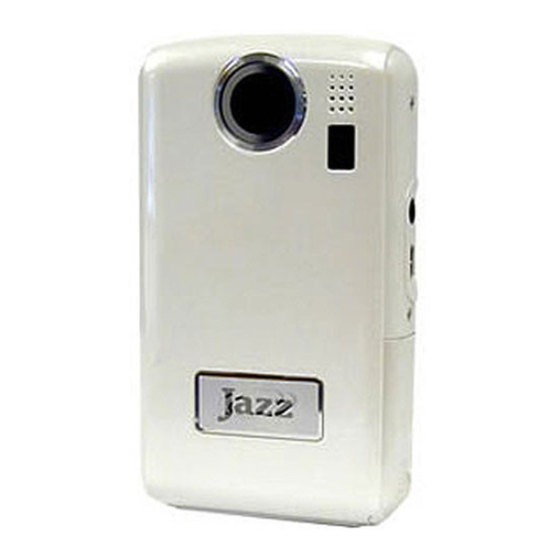
Jazz DV150 Wiring and IR Mod.
1) Remove batteries from the camera
2) Remove the 6 screws which hold the case together. The two screws on the bottom of the
camera are located under the serial number label.
3) Open the battery door. GENTLY pry open the case from the bottom. Then push the front of
the case upward to dislodge the plastic case catches on the top of the camera
4) Now that the front of the case is removed, disconnect the microphone from the front of the
case. Simply pull up on the rubber grommet to remove it from the mount hole. Remove the
screw which holds the record led in place and remove the led from under the holder
Advertisement

Subscribe to Our Youtube Channel
Related Manuals for Jazz DV150


Summary of Contents for Jazz DV150
- Page 1 Jazz DV150 Wiring and IR Mod. 1) Remove batteries from the camera 2) Remove the 6 screws which hold the case together. The two screws on the bottom of the camera are located under the serial number label. 3) Open the battery door. GENTLY pry open the case from the bottom. Then push the front of...
- Page 2 5) Pull the battery board out of its holder 6) Remove the two screws which hold the battery holder in place. Remove the battery holder 7) Remove the tape covering the speaker which is located under the battery holder, then remove the speaker.
- Page 3 10) Flip the main board over and remove the two screws which hold the switch board in place. Also, peel away the copper film from the bottom of the LCD. Note: Directly above the left screw, the copper film is soldered to the main board. Try not to tear the copper from the main board, but if it happens, it should be OK, the board will still operate.
- Page 4 12) Pins 1 and 4 are the power switch pins... pins 8 and 10 are the shutter pins. Solder the wires as shown. MAKE SURE WHEN SOLDERING THE WIRE THAT YOU DO NOT SHORT TO NEARBY PINS!!! 13) Next, we need to remove the lens from the camera and replace with a non IR coated lens. First, pull the top of the LCD away from the gray LCD holder.
- Page 5 14)Now, flip the board over and remove the 4 screws which attach the gray lcd holder to the main board. 15) Now you will see the two screws that hold the lens holder in place. Remove them and remove the lens. BE CAREFUL NOT TO SCRATCH THE CMOS SENSOR ELEMENT WHICH IS UNPROTECTED!!!
- Page 6 16) Now simply replace the old lens with the new lens. Be sure to use the screws that come with the new lens because they are longer and hold the lens better. 17) The new lens is taller than the original, so then lens protector on the front case of the camera will need to be removed.
- Page 7 24) Install the battery contact board back into the case holder. 25) Now we need to add the 5 wire This is critical to the proper operation of the Jazz camera You will solder this 5 wire to the Jazz Battery negative contact terminal...
- Page 8 Or you can drill a small hole just below the circuit board and attach the servo connector on the back of the Case right below the Lcd screen and above the button pad. Connecting the Jazz to the Bigfoot board...
- Page 9 Wiring the Optional Sister Boards to the Bigfoot board...
Need help?
Do you have a question about the DV150 and is the answer not in the manual?
Questions and answers