Table of Contents
Advertisement
Quick Links
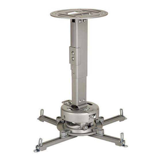
Installation and Assembly:
Projector Ceiling/Wall Mount
Models: PRS-EXA, PRS-EXA-S, PRS-EXA-W
PRS-EXB, PRS-EXB-S, PRS-EXB-W
PRS-EXC, PRS-EXC-S, PRS-EXC-W
Features:
• Continuous channel design for uninterrupted drop length or wall extension adjustments
• Safety catch designed into extension to ensure user and equipment safety
• Internal cable management within channels for clean, clutter-free appearance
• Includes PRS Series projector mount for precise image alignment
2300 White Oak Circle • Aurora, Il 60502 • (800) 865-2112 • Fax: (800) 359-6500 • www.peerlessmounts.com
Installed to
Ceiling
Max UL Load Capacity:
25 lb (11.3 kg)
Installed to Wall
(PRS-EXC models are not
wall mountable due to its
extensive reach)
ISSUED: 04-24-08 SHEET #: 055-9256-9 11-21-11
Advertisement
Table of Contents

Subscribe to Our Youtube Channel
Related Manuals for peerless-AV PRS-EXA


Summary of Contents for peerless-AV PRS-EXA
- Page 1 Installation and Assembly: Projector Ceiling/Wall Mount Models: PRS-EXA, PRS-EXA-S, PRS-EXA-W PRS-EXB, PRS-EXB-S, PRS-EXB-W PRS-EXC, PRS-EXC-S, PRS-EXC-W Max UL Load Capacity: 25 lb (11.3 kg) Installed to Ceiling Installed to Wall (PRS-EXC models are not wall mountable due to its extensive reach) Features: •...
-
Page 2: Table Of Contents
NOTE: Read entire instruction sheet before you start installation and assembly. WARNING • Do not begin to install your Peerless product until you have read and understood the instructions and warnings contained in this Installation Sheet. If you have any questions regarding any of the instructions or warnings, for US customers please call Peerless customer care at 1-800-865-2112, for all international customers, please contact your local distributor. -
Page 3: Parts List
(BB) inner channel (CC) cable cover (LL) Model# length part# part# part# PRS-EXA 8.69" - 12.79" 055-1779 055-1778 055-1809-2 PRS-EXA-S 8.69" - 12.79" 055-4779 055-4778 055-4809-2 PRS-EXA-W 8.69" - 12.79" 055-2779 055-2778 055-2809-2 PRS-EXB 12.69" - 20.69" 055-1776... - Page 4 Parts may appear slightly different than illustrated. 4 of 13 ISSUED: 04-24-08 SHEET #: 055-9256-9 11-21-11...
-
Page 5: Installing Outer Channel To Ceiling Plate
Install Outer Channel to Ceiling Plate Attach outer channel (BB) to ceiling plate (AA) using four M6 x 10 mm socket pin screws (II) as shown. Tighten screws with 4 mm security wrench (L). 5 of 13 ISSUED: 04-24-08 SHEET #: 055-9256-9 11-21-11... -
Page 6: Installation To Wood Joist Ceiling Or Wood Stud Wall
Installation to Wood Joist Ceilings or Wood Stud Walls WARNING • Installer must verify that the supporting surface will safely support the combined load of the equipment and all attached hardware and components. • Tighten wood screws so that ceiling/wall plate is fi rmly attached, but do not overtighten. Overtightening can damage the screws, greatly reducing their holding power. -
Page 7: Installation To Solid Concrete Ceiling Or Concrete/Cinder Block Walls
Installation to Concrete Ceilings or Concrete/Cinder Block Walls WARNING • When installing Peerless wall mounts on cinder block, verify that you have a minimum of 1-3/8" of actual concrete thickness in the hole to be used for the concrete anchors. Do not drill into mortar joints! Be sure to mount in a solid part of the block, generally 1"... -
Page 8: Installing Inner Channel And Routing Cables
Installing Inner Channel and Routing Cables NOTE: Be certain holes on inner channel (CC) face in the same direction of opening on outer channel (BB). NOTE: Cables must be removed from projector before routing through channels. If cables are not removable from projector, routing through channels is not an option. -
Page 9: Installing Projector Mount
Installing Projector Mount Installing PRS projector mount with wall installation: Position PRS projector mount (A) to the orientation shown in fi gure 4.1 and attach to horizontal mounting plate (FF) using two M5 x 16 mm socket pin screws (GG), four fl at washers (F) and two locknuts (KK). -
Page 10: Attaching Adapter Plate To Projector
Wall installation: Insert horizontal mounting plate (FF) into inner channel (CC) as shown in fi gure 5.3. Secure horizontal mounting plate to inner channel using four socket pin screws (JJ) as shown in fi gure 5.4. fi g. 5.3 fi g. 5.4 ARROW INDICATES FRONT OF MOUNT Attaching Adapter Plate to Projector... - Page 11 Attach adapter plate (B) to projector using one screw (G, H, I, or J) for each channel as shown below. Tighten all screws, while keeping the center of gravity. Be sure that adapter plate (B) is straight. Adjust the feet of the channels to keep the adapter plate level.
-
Page 12: Projector Alignment
IMPORTANT: For security installations, insert one #10-32 x 1/4" socket pin screw (E) through projector mount assembly (A) and into connection block as shown. Tighten screw with 4mm security t-wrench (L). CONNECTION BLOCK Projector Alignment To adjust yaw (swivel): Loosen screw on projector mount assembly (A) indicated below until projector mount can be rotated. -
Page 13: Adjusting Mount Extension
Adjusting Mount Extension While supporting the weight of the projector, loosen clamp plate screws half a turn and position projector to the desired extended position. Retighten clamp plate screws securely. WARNING • On ceiling installations, clamp plate adjustment screws support weight of projector when fully tightened. Weight of the projector will need to be supported if clamp plate screws are loosened.
Need help?
Do you have a question about the PRS-EXA and is the answer not in the manual?
Questions and answers