Table of Contents
Advertisement
Quick Links
Advertisement
Table of Contents

Related Manuals for peerless-AV PSMU-PRS


Summary of Contents for peerless-AV PSMU-PRS
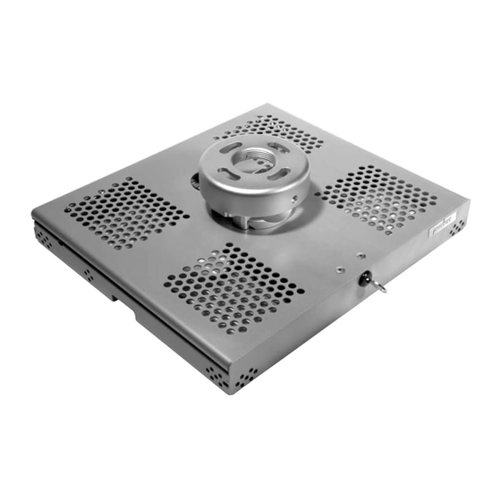
- Page 1 Tray Style Projector Mount Installation and Assembly: Models: PSMU-PRS, PSMU-PRS-S, PSMU-PRS-W Maximum Load Capacity: 30 lb (13.6 kg) 2300 White Oak Circle • Aurora, Il 60502 • (800) 865-2112 • Fax: (800) 359-6500 • www.peerlessmounts.com ISSUED 08-09-06 SHEET #: 055-9470-4 06-27-11...
-
Page 2: Tools Needed For Assembly
NOTE: Read entire instruction sheet before you start installation and assembly. WARNING • Do not begin to install your Peerless product until you have read and understood the instructions and warnings contained in this Installation Sheet. If you have any questions regarding any of the instructions or warnings, please call Peerless customer service at 1-800-865-2112. -
Page 3: Parts List
IMPORTANT! Read entire instruction sheet before you start installation and assembly. Before you start check the parts list below to make sure all of the parts shown are included. Parts List PSMU-PRS-S PSMU-PRS-W Description Qty. PSMU-PRS A projector mount assembly... - Page 4 Remove the lock plug (C) by turning the key counterclockwise. Open the top cover and attach connection block (Z) to tray (B) using two #10-32 x 3/8" serrated washer head socket pin screws (E) as shown. NOTE: Make sure that the connection block shoulder is facing the back of projector. BACK OF PROJECTOR CONNECTION...
-
Page 5: Installation To Wood Joist Ceilings
Installation To Wood Joist Ceilings WARNING • Installer must verify that the supporting surface will safely support the combined load of the equipment and all attached hardware and components. • Tighten wood screws so that projector mount assembly is fi rmly attached, but do not overtighten. Overtightening can damage the screws, greatly reducing their holding power. -
Page 6: Installation To Concrete Ceilings
Installation to Concrete Ceilings WARNING • Concrete must be 2000 psi density minimum. Lighter density concrete may not hold concrete anchor. • Make sure that the supporting surface will safely support the combined load of the equipment and all attached hard- ware and components. -
Page 7: Installation To Extension Column
Installation to Threaded Rod (Professional installation only) Thread two 3/8-16 hex thin nylon-insert locknuts (not included) on two 3/8-16 threaded rods (not included) to the desired height of projector mount assembly. Attach projector mount assembly (A) to two 3/8-16 threaded rods using two 3/8-16 hex thin nylon-insert locknuts as shown in fi... -
Page 8: Installation Of Projector
Open the mount and remove thumb screw (D) as shown. NOTE: The upper tray of the mount will now slide off of the lower tray. Installation of Projector Flip projector upside down. Attach lower tray to the bottom of the projector using appropriate number of screws (K, L, M, N, O, P, Q, R or S), washers (I) and spacers (F) as shown. - Page 9 Slide upper tray into the lower tray as shown. UPPER TRAY LOWER TRAY Attach thumb screw (D) to mount as shown to lock the upper tray to the lower tray. UPPER TRAY LOWER TRAY 9 of 11 ISSUED 08-09-06 SHEET #: 055-9470-4 06-27-11 Visit the Peerless Web Site at www.peerlessmounts.com For customer care call 1-800-865-2112...
- Page 10 Close the mount and insert the lock plug (C) and key (X) as shown. Turn lock plug clockwise until tightly secure. NOTE: To remove key (X), key slot must be in the horizontal position. This may require that you back off 1/4 turn. IMPORTANT: Key (X) is neccesary for projector removal.
- Page 11 IMPORTANT: For security installations, insert one #10-32 socket pin screw (Y) through projector mount assembly (A) and into connection block (Z) as shown. Tighten screw with 4mm t-wrench (T). To adjust yaw (swivel) for wood stud, concrete ceiling, and threaded rod mounting applications: Loosen wood screws (V), or locknuts for threaded rods, until projector mount can be rotated.
Need help?
Do you have a question about the PSMU-PRS and is the answer not in the manual?
Questions and answers