Table of Contents
Advertisement
Quick Links
Advertisement
Table of Contents

Subscribe to Our Youtube Channel
Related Manuals for MONARCH INSTRUMENT Data Chart 1250


Summary of Contents for MONARCH INSTRUMENT Data Chart 1250
-
Page 2: Table Of Contents
TABLE OF CONTENTS 1.0 INTRODUCTION CHART SPEED TO SAMPLE SPEED REVIEWING DATA ZOOMING AND CONDITIONING DATA CUSTOMIZING TRIGGERING THE GRAPHICS LCD DISPLAY OTHER GRAPHIC MODES 2.0 INSTALLATION AND SETUP UNPACKING 2.1.1 Initial Inspection 2.1.2 Unpacking Procedure 2.1.3 Detected Damage 2.1.4 Equipment Return 2.1.5 Storage... - Page 3 This instrument is not user serviceable. For technical assistance, contact the sales organization from which you purchased the product. Monarch Instrument’s Limited Warranty applies. Warranty Conditions, Registration and Extended Warranty coverage available online at www.monarchinstrument.com.
- Page 4 WEEE NOTICE In order to comply with EU Directive 2002/96/EC on Waste Electrical and Electronic Equipment (WEEE): This product may contain material which could be hazardous to human health and the environment. DO NOT DISPOSE of this product as unsorted municipal waste.
-
Page 5: Introduction
1.0 INTRODUCTION The DC1250 is the next generation Solid State Data Recorder / Panel Indicator. This instrument has all the capability of a traditional paper recorder - variable chart speeds, the ability to review historic data, see trends and more, with a number of specific exceptions - NO PAPER to jam, no ink to smudge and no pens to clog or break. -
Page 6: Reviewing Data
REVIEWING DATA One of the biggest features of this recorder is its ability to show historic data and trends. The data on the graphics screen can be rewound like a tape recorder, scrolling back in time, displaying past data on the screen while still recording data in real time. The data can also be compressed on screen, showing a whole day or week's worth of recording on one screen, enabling trends or irregularities to be spotted easily. -
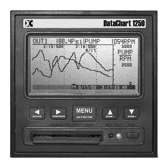
Page 7: The Graphics Lcd Display
THE GRAPHICS LCD DISPLAY DC1250 Front View showing TREND Display The above diagram is a representation of the recorder in the TREND mode. The alpha characters around the border point to various features of the unit and are described below. Not shown are the MENUS which pop up over the display. - Page 8 pressing one of the other buttons. The second function is printed on each button. Date and Time – shows the actual time of day (real time). The time is displayed user selectable in 12 or 24 hour format. The user can also select European or American formats and auto daylight savings adjustment.
-
Page 9: Other Graphic Modes
left ◄ and right ► arrow buttons. Exit the HOLD mode by pressing the MENU button. DO NOT INSERT OR REMOVE THE COMPACT FLASH CARD WHILE THE BUSY LED IS ON! OTHER GRAPHIC MODES In addition to the full screen trend mode shown section 1.6, there are two additional graphic display modes. -
Page 10: Installation And Setup
2.0 INSTALLATION AND SETUP UNPACKING 2.1.1 Initial Inspection Exercise care when unpacking the instrument from the shipping carton. The instrument is packed in a custom cardboard box to prevent damage during normal transit. If damage to the shipping carton is evident, ask the carrier’s representative to be present when the instrument is unpacked. - Page 11 installation and should be clearly marked, in close proximity to the Recorder and easily accessible to the operator. The Recorder is sized to fit in a standard ¼ DIN panel cutout of 92 x 92 mm (3.62 x 3.62 in.) and requires 140mm (7.5 inches) behind panel depth not including space for power and input source cable.
-
Page 12: Connection
2.2.1.8 Using the screwdriver, tighten both screws so that the Recorder is held firmly in place. Do not over tighten. DC Power Connector Relay Outputs Locking Bar (2) Digital Input Analog Inputs Temperature Compensator Retaining Screw (2) Fig 2.2 Rear View - Installation CONNECTION 2.3.1 Power Connections NOTE: The Recorder is designed to be panel mounted and as such... - Page 13 power and signal wires accordingly, noting carefully all polarities. Ensure that the unit is properly grounded to a suitable ground within the cabinet. Identify the power connector on the rear panel in the top left corner. The power source required is clearly marked, DC with the specific voltage level. (Refer to Figure 2.3). Loosen the screws on the terminal block and insert the exposed conductor cable from the power supply below the screws, under the metal plate.
- Page 14 The screw terminals are marked on the rear panel - there are four connections per channel. The high or positive signal marked IN+, and a low or common signal marked IN-. The terminal marked Vo is the Auxilliary voltage output used to drive external sensors at +5Vdc and a maximum of 30mA.
-
Page 15: Cleaning
The Ethernet Connection is an option and will be installed only if specifically ordered. It is a 10MHz TCP/IP port that allows the user to program the recorder remotely, start or stop recording and download real time data. Refer to the separate manual that is supplied with the ethernet interface option. 2.3.6 USB Port (Option) The USB Port is an option and will be installed only if specifically ordered. -
Page 16: Alarms
value is equivalent to -62.5 PSI and should be set to this value, and the HI SCALE is set to "250". The engineering units are set to "PSI". The display will now show zero to 250 PSI for 1 to 5 Volts input. The linear scaling is shown in Figure 2.5 on the previous page. ALARMS The recorder has four programmable internal alarms with dual relay output. -
Page 17: Memory Cards
ALARMS menu by selecting the ENABLE option so that no appears to the left of this option. Once everything is set, select ENABLE once more to activate the alarm, indicated by the presence of the . (Refer to Section 4.2) When setting up alarms, you may get unexpected results from the relays if they are enabled. - Page 18 If you show the Card Status window (MENU - CARD STATUS), it will indicate how much time is left on the card. It also displays the current Filename that is being used for recording. The files on the card are in DOS standard format and can be managed on any Windows™...
-
Page 19: Basic Operating Instructions
3.0 BASIC OPERATING INSTRUCTIONS The Basic mode of operation encompasses those functions that would be done on a routine basis and relate primarily to viewing and reviewing data with some use of the menu system. The advanced mode, while technically still simple to operate, involves setting up the unit and would typically need to be done only once. -
Page 20: Zooming Data (Amplification)
Note that compression displays peak values (both high and low). Thus even though data is compressed, all amplitude information is present on the display. At compressions of 16 times or greater, the redraw time of data on the screen slows down due to the large amounts of data that must be manipulated. -
Page 21: Cursor Id
The menu has multiple levels. An option with a secondary level is indicated by .. after the name. Access to the various levels can be controlled by a password (Refer to section 3.5.8). The following menu options have minimal function: 3.5.1 EXIT! When the menu is displayed, it defaults to the EXIT selection. -
Page 22: View File
data scrolls beneath it. This method can be used to accurately identify unique points on the graphics display no matter how busy the traces appear. To return to normal (real time) mode, press the MENU button. Note that entering the Cursor ID mode does not affect the real time acquisition of data. -
Page 23: Event Triggering
3.5.8 PASSWORD (PROTECTION) To set, reset or change a password, press the MENU button, use the Up Arrow (▲) or Down Arrow (▼) button to highlight PASSWORD and then press the MENU button. This menu option may be password protected. Follow the prompts. - Page 24 1 2 3 4 X ↑↓ →← H F From left to right these icons are as follows: 1 2 3 4 - These icon symbols indicate that the alarms are enabled (1 is Alarm 1 etc.). Any number of them may be present depending on how the alarms have been set up. If an alarm is enabled a solid block will be present.
- Page 25 TOP LEVEL MENU OVERVIEW Top Level Level 1 Function EXIT Exits from Menu ALARM RESET Resets any Alarms. Note if Alarm is still active it will set again. Auto exits menu RECORD MODE Enter Password (if set) then press MENU. Stop Recording Start Recording TRIGGERED...
-
Page 26: Advanced Setup
4.0 ADVANCED SETUP The ADVANCED SETUP menu may be password protected. This CHAN A SETUP.. menu is used to program the various operating parameters of the CHAN B SETUP.. recorder. This includes analog inputs, alarms, display settings, the ALARMS.. clock and various trigger modes. RELAYS.. -
Page 27: Alarms
CHAN TAG Enter a Channel Tag Identifier up to 5 Characters. Use ▼▲► keys. ◄ to clear or escape. Use MENU key to Save and Exit CHAN UNITS Default value is Range value Enter a Channel Units. Some Ranges have defaults. -
Page 28: Relays
LATCHING Toggle using MENU - make alarm latching Prevents a low alarm activating until the setpoint has LOCK OUT been exceeded once DEFAULT RELAYS This option is used to program the physical relay outputs. There are two relays and each is programmed independently. -
Page 29: Data Card
Set location of Time (& Date) imprint to TOP of TREND Set location of Time (& Date) imprint to MIDDLE MIDDLE of TREND Set location of Time (& Date) imprint to BOTTOM BOTTOM of TREND MENU TIMEOUT MENU will never Collape (and revert to display NEVER mode) Choose MENU TIMEOUT from 30 seconds... -
Page 30: Clock
CLOCK This option allows the user to set the time and date and determine what is displayed for time on the bottom right of the display. Use the Up Arrow (▲) or Down Arrow (▼) buttons to scroll and highlight CLOCK.. and press the MENU button. The menu options are shown below. MODES TIME OF DAY Select Time Display as Real Time Clock... -
Page 31: Sample Trigger
SAMPLE TRIGGER This option allows the user to program what will trigger a change of sample rate in the displayed or recorded data. Use the Up Arrow (▲) or Down Arrow (▼) buttons to scroll and highlight SAMPLE TRIG.. and press the MENU button. The menu options are shown below. Note that if an event is selected to change the sample rate, when exiting the menu the sample rate menu will be displayed. -
Page 32: Miscellaneous
5.0 MISCELLANEOUS CALIBRATION Before leaving the factory, the recorder is calibrated using NIST traceable sources. The calibration values are stored in non-volatile memory. The unit is calibrated to meet specification but the user may wish to re-calibrate the unit, or calibrate specific input ranges for increased accuracy. - Page 33 CURRENTS which are derived from the Hi Volts calibration value require an additional span calibration to correct for the external resistor (Customer supplied) – each channel FREQ and SPEED requires only a time base calibration shared for both channels In general, to calibrate an analog input, first set the specific channel to an input type in the ADVANCED SETUP MENU - CHANNEL SETUP - INPUT TYPE (see Section 4.1).
- Page 34 Recommended procedure for full initial calibration, in this order: - Calibrate 250 mV range, both channels using a calibrated source. - Calibrate 5.00 V range, both channels using a calibrated source - Calibrate any T/C range, both channels using the NOMINAL method. - Calibrate any RTD range, both channels using NOMINAL method - Calibrate any current range, both channels using NOMINAL method - Calibrate any Tach range, either channel using a calibrated signal source.
-
Page 35: Specifications
SPECIFICATIONS Input Power: Recorder: 9Vdc +0.5V @ 5VA (depends on external loads) External AC Universal adaptor: 100 – 240Vac 50/60 Hz Optional isolated: 12 – 24 Vdc input (not compatible with battery backup option) Battery Option: Internal battery pack provides uninterrupted operation during black out. - Page 36 Dimensions: Front panel 96mm x 96mm (1/4 DIN) x 152mm (3.78 x 3.78 x 6 inches). Environmental: Indoor Use Only Installation Category II per IEC 664 Pollution Degree Level II per IEC61010-1 Altitude up to 2,000 m Temperature -10 °C to 50 °C operating per IEC61010-1 Humidity Maximum relative humidity 80% for temperatures up to 31 °C decreasing linearly to 50% relative humidity at 40 °C.
- Page 37 APPENDIX A - UNITS LABEL CHARACTERS The following is a list of the characters are available any place text can be entered. The list will start with the A character (underlined) and the UP and DOWN arrows move through the list in order left to right.
- Page 38 FILE NOT FOUND Failed attempt to read a data file or configuration file due to the fact that no such file exists on the memory card. Get the correct card. FORMAT CARD Card is incompatible or unformatted. Requires formatting. OVERWRITE CONFIG. FILE? A config file already exists on the memory card. Writing to the card will overwrite this existing file.
Need help?
Do you have a question about the Data Chart 1250 and is the answer not in the manual?
Questions and answers