Sungrow PVS-24MH User Manual
Pv array combiner box
Hide thumbs
Also See for PVS-24MH:
- User manual (56 pages) ,
- User manual (53 pages) ,
- User manual (74 pages)

Related Manuals for Sungrow PVS-24MH


Summary of Contents for Sungrow PVS-24MH
- Page 1 User Manual PVS-24MH/20MH/16MH PV Array Combiner Box PVS-24MH_20MH_16MH-UEN-Ver11-201911...
-
Page 3: Table Of Contents
Contents About This Manual ..............1 Validity ..................1 Contents ..................1 Target Readers ................1 How to Use this Manual ............2 Others ..................2 Symbol Explanation ..............2 Figures Explanation ..............3 Safety Instructions ..............4 Product Description ............7 System Introduction ..............7 Main Features ................ - Page 4 Cable Layout ................29 Communication Settings ............30 5.6.2 Setting Communication Address ..........31 5.6.3 Setting String Input Number ............ 31 Start/Stop ................. 32 Commissioning ..............33 Routine Maintenance ............34 Overview .................. 34 Replace the Fuse ..............34 Replace the Sealing Strip ............35 Troubleshooting ..............
-
Page 5: About This Manual
1 About This Manual 1.1 Validity This manual is valid for the following PV array combiner boxes: PVS-24MH PVS-20MH PVS-16MH 1.2 Contents Safety instructions Safety instructions for the installation, operation, commissioning and maintenance of PVS. ... -
Page 6: How To Use This Manual
PVS-16MH The electrical structure, installation and use method of PVS-20MH / PVS-16MH are the same with that of PVS-24MH. The only difference between them is the numbers of DC input strings. 1.6 Symbol Explanation This manual contains important safety and operational instructions that must be accurately understood and followed during the installation and maintenance of the equipment. -
Page 7: Figures Explanation
User Manual 1 About This Manual CAUTION indicates a hazard with a low level of risk which, if not avoided, will result in minor or moderate injury. NOTICE indicates a situation which, if not avoided, will result in equipment malfunction or property damage. NOTE indicates additional information, emphasized contents or tips to help you solve problems or save time. -
Page 8: Safety Instructions
2 Safety Instructions This chapter describes some important safety instructions about PVS. Please read the manual carefully before installation. If any device damage occurs when ignoring the safety instructions, our company has the right to exclude all warranty claims. Lethal Voltage! ... - Page 9 User Manual 2 Safety Instructions High voltage is present inside the device! Follow all the warning signs in the device. Respect all the safety instructions in this manual and other document. The ground cable must be grounded properly, otherwise, ...
- Page 10 2 Safety Instructions User Manual Make sure the terminals are firmly connected during wiring. If the cable copper core and the terminals are not connected firmly, terminals will be over-heating and burnt. Anti-flaming cables with multi-strand are advisable and the cable cross-sectional area should be no less than the recommended value.
-
Page 11: Product Description
3 Product Description 3.1 System Introduction For a large-scale grid-connected PV system, it is common to install a DC combining device between PV modules and inverters to minimize cable connections, facilitate maintenance and enhance reliability. PVS is designed for meeting these requirements, which provides a Turnkey solution for PV plant systems. -
Page 12: Main Features
C: Equipped with monitoring function D: High voltage, up to 1,500Vdc Model Max.Number of PV strings Monitoring function PVS-24MH PVS-20MH PVS-16MH 3.4 Dimensions The dimensions of the PVS are shown in the figure below (take PVS-24MH for example). -
Page 13: Identifying The Pvs
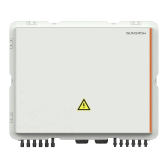
User Manual 3 Product Description 3.5 Identifying the PVS The appearance of the PVS is shown in the figure below (take PVS-24MH for example). Name Description Lockhole... -
Page 14: Mechanical Installation
Note 1: * is optional accessory. Note 2: a) is intended for PVS-16MH; b) is intended for PVS-20MH; and c) is intended for PVS-24MH. 4.2 Installation Site Requirements With IP67 protection degree, the PVS can be installed outdoors. Please meet... -
Page 15: Installation Tools
User Manual 4 Mechanical Installation the following requirements: Take the dimensions and weight of the PVS into account when selecting the installation location. The PVS should be installed as close to the PV modules as possible for easier current confluence and lower cable costs. ... -
Page 16: Installing Pvs
5 Electrical Installation User Manual Dust mask Earplugs Goggles Insulated shoes Vacuum cleaner Heat shrink tubing Heat gun Installation tools φ11 Hammer drill Electric M10 Screwdriver Wire stripper screwdriver Hydraulic pliers Crimping tool terminal Wire cutter wrench 4.4 Installing PVS Overview The PVS is fixed to the installation surface via the hangers in the scope of delivery. - Page 17 User Manual 4 Mechanical Installation 4-Φ12 x 25 Fixing PVS to Installation Surface On site, the PVS can be installed on the bracket or the back of the PV module. Mark positions on the back of the PV module according to the distance Step 1 between the hangers, and drill holes according to the marks.
- Page 18 5 Electrical Installation User Manual Item Name Description PV module bracket...
-
Page 19: Electrical Installation
5 Electrical Installation 5.1 Internal Structure Two schemes are available for the combiner box: floating grounding and negative grounding. Correspondingly, the internal structural diagram differs. Fig. 5-1 Floating grounding Fig. 5-2 Negative grounding Description DC+ fuse cartridge Ground copper bar RS485 ports DC- fuse cartridge... - Page 20 5 Electrical Installation User Manual Description The monitoring board SPD (Surge protection device) Load-break switch * The figure and the configurations are for reference only, and the actual product shall prevail. The Monitoring Board The monitoring board monitors the current of each string. The monitored current value is sent to the PC through RS485.
-
Page 21: Waterproof Terminals
User Manual 5 Electrical Installation 5.2 Waterproof Terminals Gland Terminals MC4 Connector Label Description Model Cable(mm) Label Negative pole INPUT DC+ input waterproof terminal M24x1.5 2x6.7 (MC4) Positive pole INPUT DC- input waterproof terminal Communication MONITOR input waterproof INPUT terminal PG-11 5~10 Communication... -
Page 22: Wiring Preparations
5 Electrical Installation User Manual 5.3 Wiring Preparations Open the door. Step 1 Remove the protection cover. Step 2 Step 3 Turn the load-break switch to the "OFF" position. Fig. 5-3 Load-break switch state When the Load-break switch is turned to the OFF position, risks may still result from inadvertent closing operation. -
Page 23: Connections
User Manual 5 Electrical Installation Disconnect the fuse which has been installed in the fuse holder before Step 4 delivery. Before starting electrical connections, open the fuse cover to disconnect the fuse. 5.4 Connections 5.4.1 Input Connections Lethal electric shock or serious burn from high voltage present on PV string! Observe the following safety instructions related to the wiring operations: ... - Page 24 5 Electrical Installation User Manual Brief Description There are two types of input terminals: gland waterproof terminals and MC4 terminals. MC4 Terminal Strip off 10mm insulation layer from the positive and negative DC cable. Step 1 Step 2 Assemble the cable ends with crimp contacts by crimping pliers. Connect the cables according to the method illustrated below.
- Page 25 User Manual 5 Electrical Installation After wiring, never use fireproof mud to seal the gap around MC4 terminal on the bottom of the PVS. Gland Terminal Loosen the "INPUT DC+" union nut of gland terminals. Step 1 Insert the “PV1+” cable through terminals of "INPUT DC+", and connect Step 2 the cable to the “PV1+”...
-
Page 26: Output Connections
5 Electrical Installation User Manual As shown in the following figure, connect the terminal to the Step 6 corresponding terminal of the PVS. Follow the same procedure to connect the rest of cables. Comb all the input cables together with cable ties and firm them onto the cable support bar. Appropriate cable bending space shall be ensured. - Page 27 User Manual 5 Electrical Installation φ11 Φ13 Φ16.5 Fig. 5-5 Wiring terminals Brand Figure Specification Figure (a) φ11 Nader Figure (b) φ16.5 Beijing People Figure (c) φ13 telergon Wiring Procedure Insert the “DC+” cable through “OUTPUT DC(+)” terminal. Enough Step 1 cable bending space should be ensured.
-
Page 28: Grounding Connections
5 Electrical Installation User Manual Copper Copper Spring Flat connection Bolt bus bar washer washer terminal Fig. 5-7 Al wiring connection Copper Cu-Al transition Spring Flat Bolt bus bar washer washer Screw the bolt of the gland terminal tight clockwise. Step 4 Make sure that the nuts have been screwed into place. - Page 29 User Manual 5 Electrical Installation Relevant standards must be observed. Ground cables must be connected firmly with both device and ground terminals. Ground resistance shall be measured after finishing ground connections, and the measured values should not be over 1Ω. Description of Wiring Terminals Two types of grounding holes are reserved on the PVS, including φ6 and φ10.
-
Page 30: Communication Connections
5 Electrical Installation User Manual According to the sequence of screw, spring washer, flat washer, OT Step 5 terminal and ground hole to connect the OT terminal to the ground copper bar. For the fastening torque, refer to the "Tab. 5-1 Wiring requirements"... - Page 31 User Manual 5 Electrical Installation Insert wires into bottom of wiring holes A1, B1, and FG. Among them: Step 5 − Connect communication cable RS485-A to A1; − Connect communication cable RS485-B to B1; − Connect communication cable shielding layer to terminal FG. Loosen the screwdriver to let the leaf spring connect to the cable.
-
Page 32: Bottom Wiring
After installation or commissioning, ensure the door and the cover of the key is locked to avoid the water is in. If such a situation occurs, Sungrow takes no responsibility for this. 5.4.5 Bottom Wiring The cables wired at the bottom of the PVS should be bent for some surplus. -
Page 33: Cable Layout
User Manual 5 Electrical Installation After installation or maintenance, close and lock the door, and tighten the key-hole waterproof cover to avoid water penetration. Each cable should be bent for some surplus. Do not tension it. 5.5 Cable Layout Lay the cables connected the PVS and external devices in the cable trench for easy installation and maintenance. -
Page 34: Communication Settings
5 Electrical Installation User Manual 5.6 Communication Settings Communication parameters of PVS can be set and viewed on the monitoring board, as shown below. A LED display The LED display is used to display the electrical parameters and communication parameters of the PVS. B Key buttons The left one is K1 and the right one is K2. -
Page 35: Setting Communication Address
In this section, brief description is given by using an example in which the device type is PVS-24MH and the number of strings actually connected is 23. Press and hold K2 for 2s until the last three digits of the LED display Step 1 "P=0"... -
Page 36: Start/Stop
5 Electrical Installation User Manual − "0" is corresponding to "Not connected"; and − "1" is corresponding to "Connected". If the number of strings actually connected is 23, and the 24 string is set Step 4 to "Not connected", the display of the LED is as follows: Press and hold both K1 and K2 for 2s to save the foregoing setting. -
Page 37: Commissioning
6 Commissioning Check if the PVS can operate normally after installation: Connect the connection terminal of each PV string. Step 1 Measure the input voltage of positive pole and negative pole of each Step 2 input to make sure they are basically same and the positive pole and negative pole are connected correctly. -
Page 38: Routine Maintenance
7 Routine Maintenance 7.1 Overview Due to ambient temperature, relative humidity, windblown dust and vibrations, components of PVS will get aging. It is necessary to do the routine maintenance work periodically on the device. Only qualified electricians can do the maintenance work described in this chapter. -
Page 39: Replace The Sealing Strip
7.3 Replace the Sealing Strip The sealing strip inside the PVS is located in the PVS internal door cover, as shown by A in the figure. If it is damaged by non-human factors, please contact Sungrow immediately to replace the PVS door cover. -
Page 40: Troubleshooting
8 Troubleshooting 8.1 Before Troubleshooting Please notice the following items before troubleshooting: Disconnect the load-break switch before operation. Please do not touch the bare metal parts of the copper bar under the protection plate. Pull the fuse holder for maintenance of the combining busbar and to disconnect the input cable. - Page 41 User Manual 9 Troubleshooting Fault Possible cause Method of correction Contact us for replacement of “RUN” does not flash. Faulty CPU board the monitoring unit. Failure surge Replace surge protection “SPD” lights up. protection device device in time. Other Faults Fault Possible cause Method of correction...
- Page 42 9 Troubleshooting User Manual If there are any problems in using the PVS, please contact Sungrow. E-mail address: service@sungrowpower.com For better service, please provide us with the following information: Type of the PVS Serial number of the PVS ...
-
Page 43: Appendix
9 Appendix 9.1 Technical Data Model PVS-16MH PVS-20MH PVS-24MH Max. PV string voltage 1500Vdc Max. PV string parallel inputs Rated fuse current for 15 A / 20 A each string (replaceable) Switch disconnector 400 A 1500 Vdc, type 2 Input terminal type... -
Page 44: Cable Requirement
Evidence Sungrow Power Supply Co., Ltd. needs the users to provide the receipt invoice and the date you purchase. Meanwhile the trademark should be clearly legible. Otherwise Sungrow Power Supply Co., Ltd. has the right to exclude liability claims. -
Page 45: Contact Information
In case of unforeseen calamity or accidents Where fault is caused by any of the above and users have the relevant demand, Sungrow will do the paid maintenance work to the device after judgment. Specifications are subject to changes without advance notice. - Page 46 Sungrow Power Korea Limited Tokyo Seoul +827077191889 + 81 3 6262 9917 service@kr.sungrowpower.com japanservice@jp.sungrowpower.com Malaysia Philippines Sungrow SEA Sungrow Power Supply Co., Ltd Selangor Darul Ehsan Mandaluyong City +6019897 3360 +639173022769 service@my.sungrowpower.com service@ph.sungrowpower.com Thailand Spain SungrowThailand Co., Ltd. Sungrow Ibé rica S.L.U.
- Page 47 User Manual 9 Appendix U.S.A, Mexico Sungrow Power UK Ltd. Sungrow USA Corporation Milton Keynes PhoenixArizona +44 (0) 0908 414127 +1833 7476937 service.uk@sungrow.co techsupport@sungrow-na.com Vietnam Sungrow Vietnam Hanoi +84 918 402 140 service@vn.sungrowpower.com...
Need help?
Do you have a question about the PVS-24MH and is the answer not in the manual?
Questions and answers