Table of Contents
Advertisement
Quick Links
Advertisement
Table of Contents

Related Manuals for Sungrow SunBox PVS-8M


Summary of Contents for Sungrow SunBox PVS-8M
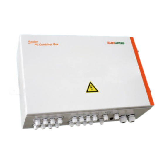
- Page 1 SunBox PVS-8M/PVS-16M PV Array Combiner Box User Manual...
-
Page 3: Table Of Contents
Contents 1 About This Manual ..............1 Contents ........................1 Target Readers ......................1 How to Use this Manual ..................1 Other Information ....................2 Symbol Explanation ....................2 ... - Page 4 4.3.7 Communication Connections ................24 4.3.8 Installation of fuses ....................27 4.3.9 Bottom wirings ......................27 Communication address settings ..............28 Start/Stop of operation ..................31 5 Commissioning............... 32 6 Routine Maintenance ............. 33 ...
-
Page 5: 1 About This Manual
1 About This Manual 1.1 Contents Safety instructions Safety instructions for the installation, operation, commissioning and maintenance of PVS. Product description Location of PVS in the PV system, structure, function and classification. Installation guide The installation methods and electrical connections of PVS. ... -
Page 6: Other Information
To satisfy your requirements, we have also provided PVS-6M and PVS-12M with a DC input string number of 6 and 12 respectively. Their electrical structure, installation and use are the same with those of SunBox PVS-8M/PVS-16M. This manual takes SunBox PVS-8M/PVS-16M for example. For installation and operation of combiner box with other inputs, please refer to this manual. -
Page 7: Picture Explanation
User Manual 1 About This Manual NOTICE indicates a situation which, if not avoided, will result in equipment malfunction or property damage. NOTE indicates additional information, emphasized contents or tips to help you solve problems or save time. The following symbols on the device enclosure must be paid attention to. Symbols Explanation Risk of electric shock! If not avoided, lethal hazard can be caused. -
Page 8: 2 Safety Instructions
2 Safety Instructions This chapter describes some important safety instructions about SunBox PVS. Please read the manual carefully before installation. If any device damage occurs when ignoring the safety instructions, our company has the right to exclude all warranty claims. Lethal Voltage! ... - Page 9 User Manual 2 Safety Instructions High voltage is present inside the device! Follow all the warning signs in the device. Respect all the safety instructions in this manual and other documents. The ground cable must be grounded properly, otherwise, ...
- Page 10 2 Safety Instructions User Manual Make sure the terminals are firmly connected during wiring. If the cable copper core and the terminals are not connected firmly, terminals will be over-heating and burnt. Anti-flaming cables with multi-strand are advisable and the cable cross-sectional area should be no less than the recommended value.
- Page 11 User Manual 2 Safety Instructions Touching or improper operation on the PCB or other sensitive components may damage the device. Do not touch any parts inside the cabinet other than the connection terminals. Respect all ESD related safety regulations and wear antistatic wrist strap.
-
Page 12: 3 Product Description
The PV generation system including a PVS is shown in Fig. 3-1. Fig. 3-1 Composition of PV generation system Tab. 3-1 Device in Fig. 3-1 Device PV arrays SunBox PVS-8M/PVS-16M combiner box Inverter Data acquisition device Environment monitoring device Grid For PVS-8M, up to 8 PV strings can be connected to the input side. -
Page 13: Demonstration Of The Type
User Manual 3 Product Description PVS has the following features: Meet outdoor installation requirement Connect to multiple PV inputs with fuse for each input (can be replaced to other degree) PV-specific high voltage SPD equipped, lightening protection function for positive and negative pole ... -
Page 14: Identifying The Pvs
3 Product Description User Manual 3.3 Identifying the PVS PVS-8M/PVS-16M is shown in the following picture Name Description Lockhole Positive pole of DC input INPUT DC+ (unused terminals must be sealed) Negative pole of DC input INPUT DC- (unused terminals must be sealed) Ground terminal Equivalent potential connection terminal MONITOR... -
Page 15: Fuse Rating
User Manual 3 Product Description 3.4 Fuse rating In power system, fuses are used for over-current protection. Choosing right-rating fuses is very important to ensure safety operation. The minimum current rating of a fuse can be calculated with short circuit current (Isc) of PV arrays. -
Page 16: 4 Installation Guide
4 Installation Guide 4.1 Checking before installation The delivery content of the combiner box is shown below: PV array combiner box User Manual Warranty card Certificate card Test report Check the completeness of the delivery according to the package list inside the crate. -
Page 17: Installation Site Requirements
User Manual 4 Installation Guide 4.2.2 Installation site requirements With IP65 protection degree, the PVS can be installed outdoors. Please meet the following requirements: Dimensions and weight of PVS should be considered sufficiently). Ambient temperature -40℃~+70℃; Relative humidity 0~99%. ... -
Page 18: Installation Method
4 Installation Guide User Manual If this plastic buckle is missing during transport, the normal function of the PVS is not affected. 4.2.4 Installation Method PVS has two installation methods: vertical installation and horizontal installation. Solution 1: Horizontal installation Horizontal installation is applied to distributed PV plant and on rooftop. Horizontal installation steps Measure the distances of the hangers of the PVS and mark positions on the Step 1... - Page 19 User Manual 4 Installation Guide Install PVS upside down is strictly forbidden. Wall-mounted: fix PVS to the PV array’s installation frame through the mounting holes of the PVS by 2 or 4 M10×30 bolts Column-mounted: use hold hoop and steel angle as fixture to fix to the support column.
-
Page 20: Electrical Installation
4 Installation Guide User Manual Fig. 4-2 Drill holes (unit in mm) As shown in Fig. 4-3, install PVS by hexagon nut and hexagon bolt. From left Step 2 to right: bolt, PVS hangers, support, flat washer, spring washer and nut. Torque: 18N.m. -
Page 21: Water-Proof Terminals And Wirings
User Manual 4 Installation Guide Description DC+ fuse cartridge DC- fuse cartridge RS485 ports. Ground terminal Output of DC positive pole Output of DC negative pole DC switch Power board Push switch (switch between current and communication parameter) Protocol switch (setting communication protocol) Dip switch (setting communication address) LED display (can display current, baud rate and communication address) Indicators, from left to right:... -
Page 22: Wiring Preparations
4 Installation Guide User Manual Fig. 4-4 Size and type of water-proof terminals Label Description Model Cable(mm) Positive pole input INPUT DC+ M24*1.5 waterproof terminal Negative pole input INPUT DC- M24*1.5 waterproof terminal Communication input Monitor Input PG-11 waterproof terminal 5~10 Communication output Monitor Output... -
Page 23: Input Wiring And Connections
User Manual 4 Installation Guide (3) Remove key (4) Pull down the metal buckle (“A” in above figure) Remove the protection cover. Step 2 Turn the switch to “OFF” position. Step 3 Remove fuse Step 4 4.3.4 Input wiring and connections High voltage is present inside the device! ... - Page 24 4 Installation Guide User Manual Loosen the union nut of water-proof terminals. Step 1 Insert the “PV1+” cable through terminals of positive input area, and connect Step 2 the cable to the “PV1+” terminal inside the device. Enough wire bending space should be ensured.
- Page 25 User Manual 4 Installation Guide section), see the following figure. As shown in the following figure, connect the terminal to the corresponding Step 7 terminal of the combiner box. Notice: press the bolt to the side with indentation during fixation. Make sure the terminal is inserted into the combiner box as much as possible.
-
Page 26: Output Wiring And Connections
4 Installation Guide User Manual Fig. 4-5 Diagram of cabling route 4.3.5 Output wiring and connections Lift the protective cover upwards. Then loosen the nut from water-proof Step 1 terminals. Insert the “DC+” cable through “DC Output (+)” terminal. Enough cable Step 2 bending space should be ensured. - Page 27 User Manual 4 Installation Guide − 1. Use hexagon spanner to remove the nut; − 2. Insert DT terminal into the output terminal; − 3. Use hexagon spanner to tighten the nut. Screw the bolt of the water-proof terminal tight clockwise. Step 6 Connect cable “DC-”...
-
Page 28: Ground Wiring And Connections
4 Installation Guide User Manual Make sure that the nuts have been screwed into place. If the cable conductor has not been connected firmly, long-time work may burn the terminal. Stranded flame-retarded copper wire shall be used, and its size shall be over the recommended value as described in 8.1.2. - Page 29 User Manual 4 Installation Guide Fig. 4-6 Communication connection Upper terminal connects to input and lower terminal connects to output. User may adjust according to real need. Unscrew the water-proof terminals “Monitor Input” and “Monitor Output”. Step 2 Pull the communication cable inside the PVS through the water-proof Step 3 terminals.
- Page 30 4 Installation Guide User Manual Communication cable must be shielded twisted pair cable. Communication unstable or communication failure may follow if otherwise. Communication cable should be far away from the high voltage cable. Place the communication cables and power cables in parallel or strap them together is strictly forbidden.
-
Page 31: Installation Of Fuses
User Manual 4 Installation Guide If the PVS is equipped with optional PV internal power supply, monitor can wok normally when the PV voltage meet the switch power supply’s nominal work power supply range. 4.3.8 Installation of fuses Proceed as follows to recover the fuse cover of the positive and negative input terminal to its original place after cable connection. -
Page 32: Communication Address Settings
4 Installation Guide User Manual key is locked to avoid the water is in. If such a situation occurs, Sungrow takes no responsibility for this. 4.4 Communication address settings Communication parameters of combiner boxes can be set and viewed on the monitoring unit, as shown below. - Page 33 User Manual 4 Installation Guide Description Function communication address, baud rate, and chassis temperature on the LED. For method of operation, refer to “Table 4-2”. Combiner box allows inquiry of communication parameters by push switch. The left switch is K1 and the right switch is K2. Particular definitions: Tab.
- Page 34 4 Installation Guide User Manual Dip-switch settings Binary address Decimal address 0000 0011 (1×2 +1×2 =3) (1×2 +1×2 +1×2 +1×2 +0× 1111 0111 +1×2 +1×2 +1×2 =247) If the code is: 1111 1000 1111 1001 …… 1111 1111 0000 0000, it is deemed 0000 0001...
-
Page 35: Start/Stop Of Operation
User Manual 4 Installation Guide Setting string input number The standard types of Sungrow PVS are: PVS-8M PVS-12M PVS-16M If the strings input are 8, 12 or 16, there is no need to set any parameter. This section introduces the communication setting method of the PVS when the string inputs are 15 (the product user received is PVS-16M). -
Page 36: 5 Commissioning
5 Commissioning Check if the PVS can operate normally after installation: Connect the connection terminal of each PV string. Step 1 Measure the input voltage of positive pole and negative pole of each input Step 2 to make sure they are basically same and the positive pole and negative pole are connected correctly. -
Page 37: 6 Routine Maintenance
6 Routine Maintenance Due to ambient temperature, relative humidity, windblown dust and vibrations, components of PVS will get aging. It is necessary to do the routine maintenance work periodically on the device. Only qualified electricians can do the maintenance work described in this chapter. -
Page 38: Replace The Sealing Strip
The sealing strip inside the PVS is located in the PVS internal door cover as shown in the following figure. It is advisable to check this sealing strip once every month. If it is damaged by non-human factors, please contact Sungrow immediately to replace the PVS door cover. -
Page 39: 7 Troubleshooting
7 Troubleshooting This chapter gives the basic troubleshooting methods for customer as a reference. 7.1 Before troubleshooting Please notice the following items before troubleshooting: Disconnect the DC switch before operation. Please do not touch the bare metal parts of the copper bar under the protection plate. - Page 40 7 Troubleshooting User Manual Fault Possible cause Method of correction Twisted pair shielded cable shall be used, with shielding layer grounded. Install a 120Ω resistor Communication Disturbance between communication failure sometimes communication line terminals A2 and B2 of the last combiner box.
- Page 41 User Manual 7 Troubleshooting Tab. 7-1 Descriptions Indicator Meaning Transmitted communication data signal indicator Received communication data signal indicator Monitoring unit running status indicator Surge protection device fault indicator Circuit breaker status indicator Monitoring unit power supply status indicator +5V plug on the monitoring unit If you have any doubt during use of this product, please feel free to contact us.
-
Page 42: 8 Appendix
8 Appendix 8.1 Technical data Types PVS-8M PVS-12M PVS-16M Max. string number Refer to nameplate (the value can be changed by Input current range replacing fuses) 200Vdc~1000Vdc Max DC voltage RS485 Communication Power for communication 2.5W IP65 Degree of protection Ambient temperature range -40℃~+70℃... -
Page 43: Cable Requirements
Evidence Sungrow Power Supply Co., Ltd. needs the users to provide the receipt invoice and the date you purchase. Meanwhile the trademark should be clearly legible. Otherwise Sungrow Power Supply Co., Ltd. has the right to exclude liability claims. - Page 44 In case of unforeseen calamity or accidents Where fault is caused by any of the above and users have the relevant demand, Sungrow will do the paid maintenance work to the device after judgment. Specifications subject to change without notice.
-
Page 45: About Us
The power rating of Sungrow products covers from several hundred watt to large mega-watt systems. The pursuit of Sungrow is to help our customers acquire stable and clean power with minimum cost, maximum reliability and enhanced safety. - Page 46 8 Appendix User Manual...
Need help?
Do you have a question about the SunBox PVS-8M and is the answer not in the manual?
Questions and answers